
Introduction to Photoresistor Integration
Integrating a light dependent resistor Arduino setup is a foundational skill in microcontroller projects, enabling applications from automated streetlights to camera exposure meters. However, moving beyond a basic blink sketch requires a rigorous approach to hardware configuration and software calibration. In 2026, the shift toward 32-bit ARM-based boards like the Arduino Uno R4 Minima has changed how we handle analog-to-digital conversion (ADC), making legacy 10-bit tutorials obsolete. This configuration guide provides a deep dive into selecting the right sensor, designing a stable voltage divider, and writing noise-resistant firmware.
Component Selection: CdS vs. RoHS-Compliant Alternatives
The most common hobbyist photoresistors are Cadmium Sulfide (CdS) cells, such as the GL55xx series. While cheap and highly sensitive to visible light, CdS is restricted under the EU RoHS Directive due to heavy metal toxicity. For commercial prototyping or eco-conscious builds, you must consider RoHS-compliant alternatives. Below is a configuration matrix comparing standard hobbyist cells with modern alternatives.
| Model / Type | Dark Resistance | Illuminated Resistance (10 lux) | Peak Wavelength | Response Time | Est. Unit Price |
|---|---|---|---|---|---|
| GL5528 (CdS) | 1 MΩ | 10 kΩ - 20 kΩ | 540 nm (Green) | 20-30 ms | $0.08 |
| GL5516 (CdS) | 0.5 MΩ | 5 kΩ - 10 kΩ | 540 nm (Green) | 20-30 ms | $0.10 |
| Excelitas VT935G (RoHS) | 1.5 MΩ | 8 kΩ - 18 kΩ | 515 nm | 15-25 ms | $0.65 |
| TI OPT3001 (IC ALS) | N/A (I2C Digital) | N/A (Lux Output) | 550 nm (Human Eye) | < 1 ms | $1.85 |
Expert Insight: If your project requires precise lux measurements rather than relative light/dark thresholds, abandon analog LDRs entirely. The spectral response of CdS cells drifts significantly with temperature and age. For precision, configure an I2C Ambient Light Sensor (ALS) like the TI OPT3001.
Hardware Configuration: The Voltage Divider Topology
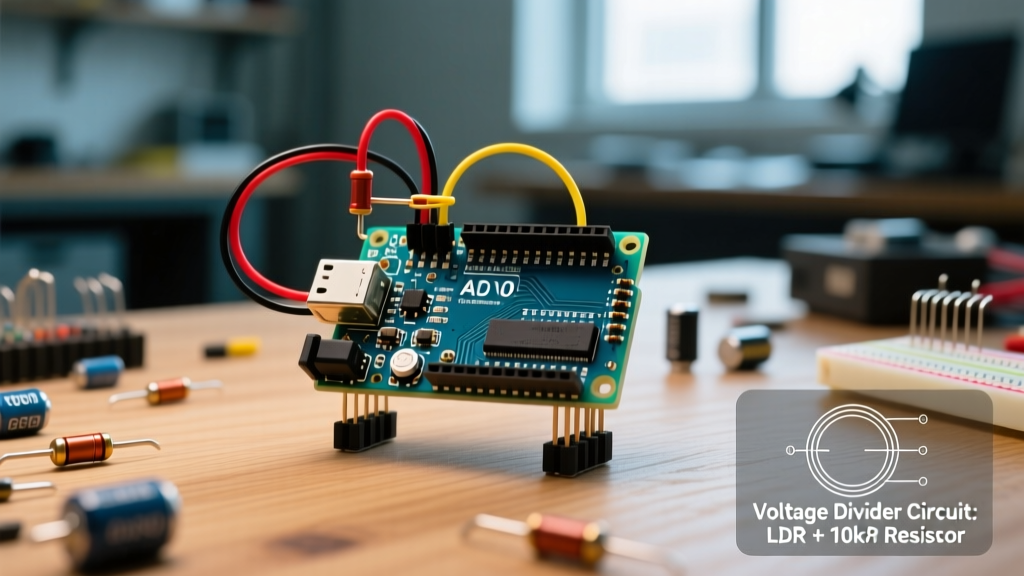
A microcontroller cannot read resistance directly; it reads voltage. Therefore, configuring a light dependent resistor Arduino circuit mandates a voltage divider. According to the SparkFun Voltage Dividers Tutorial, the output voltage ($V_{out}$) is calculated as:
V_out = V_in × (R_fixed / (R_LDR + R_fixed))
Pull-Down vs. Pull-Up Resistor Placement
The placement of your fixed resistor dictates the behavior of your analog signal:
- Pull-Down Configuration (Fixed resistor to GND): As light intensity increases, LDR resistance drops, pushing $V_{out}$ closer to $V_{in}$ (5V or 3.3V). This is the standard configuration for "turn on when bright" logic.
- Pull-Up Configuration (Fixed resistor to VCC): As light intensity increases, $V_{out}$ drops toward 0V. Use this for "turn on when dark" (nightlight) logic, as it naturally inverses the signal in hardware.
Calculating the Fixed Resistor Value
A common mistake is blindly using a 10 kΩ resistor. To maximize the ADC resolution across your specific use case, the fixed resistor ($R_{fixed}$) should be geometrically centered between the LDR's minimum and maximum expected resistances.
R_fixed = √(R_dark × R_light)
If your GL5528 measures 200 kΩ at dusk (your "dark" threshold) and 2 kΩ in direct sunlight (your "light" threshold), the optimal fixed resistor is √(200,000 × 2,000) = 20,000 Ω (20 kΩ). Using a standard 20 kΩ or 22 kΩ resistor will yield the widest voltage swing across your specific operating environment.
Wiring the Arduino Uno R4 Minima
When wiring the analog inputs, avoid pins that double as I2C or UART lines if possible, to prevent bus contention. For the Uno R4 Minima:
- Connect VCC (5V) to one leg of the LDR.
- Connect the other leg of the LDR to Analog Pin A2.
- Connect a 22 kΩ fixed resistor between A2 and GND.
- Hardware Noise Filter (Optional but recommended): Solder a 100 nF ceramic capacitor in parallel with the fixed resistor to filter out high-frequency EMI and 50/60Hz mains flicker.
Software Configuration and ADC Mapping
The transition to 32-bit ARM architectures in modern maker boards requires updating legacy code. The Arduino analogRead() Reference notes that while older AVR boards default to 10-bit resolution (0-1023), the Renesas RA4M1 chip on the Uno R4 features a 12-bit ADC (0-4095).
Handling 12-Bit ADC Resolutions
If you port an old sketch to an R4 board without adjusting the math, your thresholds will be off by a factor of four. Always explicitly define your ADC resolution in the setup() function to ensure cross-board compatibility:
void setup() {
  Serial.begin(115200);
  // Force 12-bit resolution on R4, ignored safely on R3
  analogReadResolution(12);
}
Implementing a Moving Average Filter
Indoor lighting powered by AC mains flickers at 100Hz or 120Hz (double the line frequency). While human eyes cannot see this, an LDR's 20ms response time is fast enough to detect it, resulting in noisy ADC readings. Instead of relying solely on hardware capacitors, implement a software moving average filter.
const int ldrPin = A2;
const int numReadings = 32;
int readings[numReadings];
int readIndex = 0;
long total = 0;

void loop() {
  total = total - readings[readIndex];
  readings[readIndex] = analogRead(ldrPin);
  total = total + readings[readIndex];
  readIndex = (readIndex + 1) % numReadings;

  int average = total / numReadings;
  // Map 12-bit ADC (0-4095) to percentage
  int lightPercent = map(average, 0, 4095, 0, 100);

  Serial.println(lightPercent);
  delay(10); // 10ms sampling rate
}
Calibration and Threshold Setting
Do not hardcode threshold values like if (light < 500). Environmental lighting changes drastically between seasons and room layouts. Implement a dynamic calibration routine that runs on boot or via a physical push-button.
- Min/Max Calibration: Cover the sensor completely to record the baseline dark value, then expose it to a flashlight to record the max light value. Store these in the EEPROM or non-volatile memory.
- Hysteresis Implementation: To prevent a relay from rapidly clicking on and off when ambient light hovers exactly at your threshold, implement a hysteresis band. If the turn-on threshold is 2000 (12-bit), set the turn-off threshold to 1800. This 200-point deadband eliminates oscillation.
Troubleshooting Common LDR Failure Modes
Even with perfect wiring, photoresistors exhibit physical quirks that can break a production project. Consult this troubleshooting matrix if your light dependent resistor Arduino build is behaving erratically.
| Symptom | Underlying Cause | Engineering Solution |
|---|---|---|
| Readings slowly drift upward after turning on. | Thermal Drift: CdS cells have a negative temperature coefficient. As ambient or self-heating occurs, resistance drops. | Keep LDRs away from onboard voltage regulators. Implement a software baseline calibration 60 seconds after boot. |
| Sensor is slow to react to sudden darkness. | Asymmetric Response: CdS cells recover from dark-to-light in ~20ms, but light-to-dark decay can take 100ms+. | If fast dark-detection is critical, switch to a phototransistor (e.g., TEPT5600) which operates in microseconds. |
| ADC values fluctuate wildly (±200 points). | High Impedance Noise: In very dark conditions, LDR resistance exceeds 1MΩ, making the ADC pin susceptible to capacitive coupling and EMI. | Lower the fixed resistor value (e.g., to 10kΩ) or add a 100nF bypass capacitor directly at the analog pin. |
| "Memory Effect" (Hysteresis). | Exposure to intense light temporarily alters the crystalline structure of the CdS layer, skewing subsequent low-light readings. | Use physical hoods/shrouds to block direct, high-intensity sunlight if the sensor is meant for ambient room monitoring. |
Final Configuration Checklist
Before deploying your project to the field, verify the following:
- Calculated voltage divider matches the specific lux range of the deployment environment.
- ADC resolution is explicitly defined in the firmware to prevent 10-bit/12-bit mismatch errors.
- A 100nF ceramic capacitor is installed in parallel with the pull-down resistor for hardware debouncing.
- Software hysteresis is implemented to protect mechanical relays from rapid cycling.
By treating the light dependent resistor Arduino integration as a precise analog front-end design rather than a simple digital switch, you ensure long-term reliability, accurate data logging, and professional-grade performance in your embedded systems.