
The Hidden Cost of GPIO Mismanagement
For hardware engineers, IoT developers, and advanced makers, the transition from bare-metal microcontrollers to single-board computers introduces a unique set of friction points. Many developers lose hours to debugging when mapping the gpio pins raspberry pi header to their software stacks. A disorganized approach to physical wiring, combined with legacy Python libraries and manual deployment scripts, can turn a simple sensor integration into a multi-day troubleshooting marathon.
True workflow optimization requires treating the Raspberry Pi not just as a Linux computer, but as a deterministic hardware controller. This guide bypasses basic blinking-LED tutorials and dives deep into professional-grade workflow strategies. We will cover physical layer standardization, the migration to modern libgpiod backends for the Pi 5, containerized deployment, and advanced diagnostic tooling.
Physical Layer: Standardizing Your Hardware Interface
The 40-pin header is the physical gateway to your project, but relying on loose Dupont jumper wires is the enemy of a reproducible workflow. Signal integrity issues, specifically crosstalk on high-speed SPI or I2C lines, frequently masquerade as software bugs. Optimizing your physical workflow means choosing the right interconnect topology for your project's maturity stage.
Interconnect Topology Matrix
Selecting the wrong physical interface leads to hardware rework. Use this matrix to align your wiring strategy with your project phase:
| Method | Best Use Case | Signal Integrity | Workflow Impact |
|---|---|---|---|
| Breadboard + Cobbler | Rapid prototyping, low-speed I2C/UART | Poor (>10kHz noise prone) | High iteration speed, poor long-term reliability |
| Ribbon Cable + IDC | Testing custom PCBs, logic analyzer hookups | Moderate (crosstalk on adjacent SPI lines) | Excellent for temporary diagnostic workflows |
| Stackable HATs | Standardized sensor arrays, PoE integration | Excellent (matched impedance) | Zero wiring time, but limits custom pinouts |
| Wire-to-Board (JST) | Final deployment, industrial IoT enclosures | Superior (shielded options available) | Requires upfront crimping, guarantees field reliability |
Pro-Tip for SPI Workflows: If you are routing SPI lines (like the MOSI/MISO pins on GPIO 10 and 9) via a ribbon cable longer than 10cm, you will likely experience bit-flipping at clock speeds above 5MHz. Always route high-speed SPI directly via a custom PCB or a rigid HAT to maintain signal edge rates.
Software Stack: Navigating the RP1 Southbridge Shift
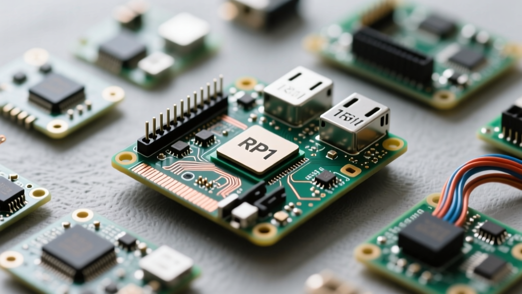
The most significant disruption to the Raspberry Pi GPIO workflow in recent years is the architectural shift introduced with the Raspberry Pi 5. Previous models (Pi 3, Pi 4) mapped GPIO directly to the Broadcom BCM2711/2837 SoC. The Pi 5 offloads I/O to the RP1 southbridge chip. This fundamentally changed how the Linux kernel interacts with the pins.
Deprecating Legacy Libraries
If your workflow still relies on the RPi.GPIO library, you are accumulating technical debt. RPi.GPIO accesses memory-mapped registers directly, which breaks on the Pi 5's RP1 architecture and requires root privileges, creating massive security and containerization hurdles.
The Optimized Stack:
- gpiozero: The definitive Pythonic interface. As of version 2.0+, it natively supports the Pi 5 by leveraging the
lgpiobackend. It abstracts pin numbering and handles cleanup automatically via Python's garbage collection. - libgpiod / lgpio: For C/C++ developers or those writing high-performance Rust bindings, interacting directly with the
libgpiodcharacter device API (/dev/gpiochip0) is the modern standard. It is kernel-compliant and does not requiresudoif the user is in thegpiogroup.
For quick terminal verification without writing a script, integrate the pinout command into your daily workflow. By typing pinout in the terminal, the Pinout.xyz ASCII diagram renders instantly, saving you from opening a browser tab mid-debug session.
Containerization: Dockerizing GPIO Access
Deploying Python scripts via scp and managing venv environments manually on the Pi is a fragile workflow. Containerizing your GPIO applications ensures that your code runs identically on your x86 development machine (via mock interfaces) and your target ARM hardware.
Passing the Character Device to Docker
Historically, Docker containers could not access GPIO without running in --privileged mode, which disables all security boundaries. The modern, optimized workflow leverages the Linux character device interface. You only need to map the specific GPIO chip device into the container.
Here is a production-ready docker-compose.yml snippet for a Pi 5 running Raspberry Pi OS Bookworm:
services:
  iot-sensor-node:
    build: .
    devices:
      - '/dev/gpiochip0:/dev/gpiochip0'
    group_add:
      - 'gpio'
    restart: unless-stopped
    environment:
      - GPIOZERO_PIN_FACTORY=lgpio
This approach guarantees that your container has the exact permissions needed to toggle pins via gpiozero without exposing the host's kernel memory or USB subsystems to the containerized application.
Diagnostic Workflows: Tracing Pin Failures in Real-Time
When a pin fails to trigger a relay or read a DHT22 sensor, the bottleneck is often a pinmux conflict or a hardware fault. Optimizing your debugging workflow means moving beyond print() statements and utilizing kernel-level diagnostics.
The Shift from raspi-gpio to pinctrl
On older Raspberry Pi OS releases, raspi-gpio was the go-to CLI tool for inspecting pin states. However, with the adoption of the RP1 chip and newer kernel device trees, raspi-gpio is deprecated. The modern workflow mandates the use of pinctrl.
To inspect the current state, drive strength, and pull-up/pull-down configuration of GPIO 17, execute:
pinctrl get 17This immediately reveals if a background systemd service or an I2C overlay has hijacked the pin, a common failure mode when integrating multiple HATs.
Hardware-Level Signal Tracing
When software diagnostics confirm the kernel is toggling the pin, but the hardware isn't responding, you must bridge the digital-physical divide. Integrate a Saleae Logic Pro 8 or a budget-friendly DSLogic Plus into your workflow. By clipping onto the physical header while simultaneously monitoring the lgpio event logs, you can instantly identify if a 3.3V logic high is sagging below the 2.0V threshold required by your external microcontroller or MOSFET gate driver due to excessive current draw.
Automating Deployment via Systemd
Stop using crontab with @reboot or the legacy rc.local script to launch your GPIO applications. These methods lack dependency management and robust logging. The optimized workflow utilizes systemd service files.
By defining a .service file, you can enforce startup delays until the dev-gpiochip0.mount is ready, automatically restart the script if a transient I2C bus lockup causes a Python exception, and pipe all stdout directly into journalctl for centralized logging.
Summary and Authoritative Resources
Optimizing your workflow around the Raspberry Pi GPIO ecosystem requires abandoning legacy habits. By standardizing your physical interconnects, migrating to libgpiod-backed libraries like gpiozero, containerizing via character device mapping, and utilizing modern pinctrl diagnostics, you transform the Pi from a hobbyist toy into a robust, industrial-grade edge controller.
For continuous reference, bookmark these authoritative resources:
- Official Raspberry Pi GPIO Documentation - The definitive guide on 3.3V logic tolerances and pinmuxing.
- gpiozero ReadTheDocs - Essential for understanding the transition to the
lgpiopin factory. - Pinout.xyz - The community-standard visual map for the 40-pin header, including alternate functions for UART, SPI, and PCM.