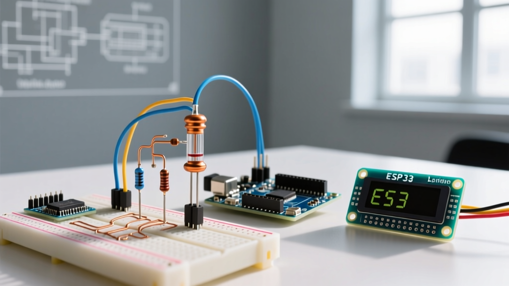

Why Your Thermistor for Arduino is Giving Erratic Readings
Integrating an NTC (Negative Temperature Coefficient) thermistor for Arduino projects is a rite of passage for makers building weather stations, 3D printer hotends, or sous-vide controllers. The most ubiquitous component in this space is the 10K Ohm NTC thermistor with a B-value of 3950. However, despite its simplicity, Makers frequently encounter erratic ADC (Analog-to-Digital Converter) readings, massive temperature drift, and baseline inaccuracies.
If your serial monitor is spitting out temperature fluctuations of ±3°C in a stable room, or your readings are offset by 5°C right out of the box, you are likely dealing with voltage reference noise, poor resistor tolerance, or self-heating errors. This comprehensive troubleshooting guide dissects the exact failure modes of thermistor circuits and provides actionable, component-level fixes to achieve ±0.5°C accuracy.
The Anatomy of Voltage Divider Wiring Errors
A microcontroller cannot read resistance directly; it reads voltage. Therefore, every thermistor for Arduino must be configured in a voltage divider circuit. The most common mistake is mismatching the physical wiring topology with the mathematical formula in the sketch.
High-Side vs. Low-Side Thermistor Placement
- Low-Side Thermistor (Thermistor to GND): The fixed pull-up resistor connects to VCC (5V or 3.3V), and the thermistor connects between the analog pin and GND. As temperature rises, thermistor resistance drops, and the voltage at the analog pin decreases.
- High-Side Thermistor (Thermistor to VCC): The thermistor connects to VCC, and the fixed pull-down resistor connects to GND. As temperature rises, resistance drops, and the voltage at the analog pin increases.
If your temperature readings move in the wrong direction (e.g., touching the thermistor makes the reading drop instead of rise), you have inverted your physical wiring relative to your code's Steinhart-Hart calculation.
The Tolerance Trap: Why 5% Resistors Ruin Accuracy
Most beginner kits include 5% tolerance carbon film resistors. If you use a 5% 10K pull-up resistor, its actual resistance could be anywhere from 9,500 to 10,500 Ohms. Because the Arduino calculates temperature based on the assumed 10,000 Ohm value, this 500-Ohm variance introduces a baseline temperature error of up to ±1.5°C before the ADC even samples the signal.
Expert Fix: Always use a 10K Ohm 1% (or 0.1%) metal film resistor for your voltage divider. They cost roughly $0.03 each in bulk and instantly eliminate baseline offset errors. Furthermore, measure your specific pull-up resistor with a multimeter and hardcode that exact value (e.g.,
10034.0) into your Arduino sketch'sSERIESRESISTORconstant.
Diagnosing ADC Noise and Grounding Issues
The ATmega328P on the classic Arduino Uno R3 features a 10-bit ADC (0-1023). When powered via a standard USB connection, the onboard 5V linear regulator introduces high-frequency switching noise. This noise manifests as ±10 to ±20 LSB (Least Significant Bit) jitter on the analog pin, translating to ±0.5°C of phantom temperature fluctuation.
Hardware Fix: The RC Low-Pass Filter
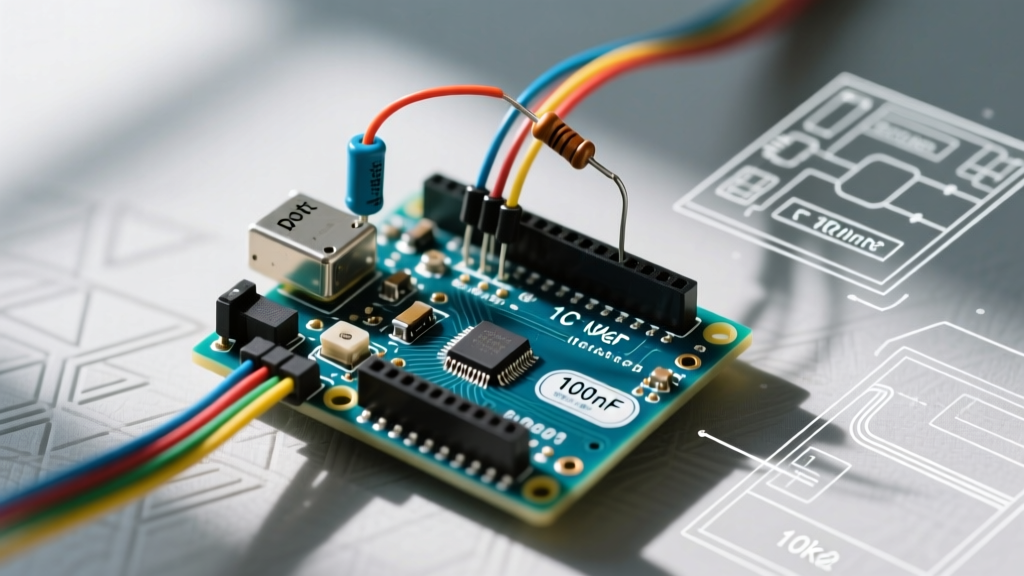
Before relying on software averaging, clean the signal at the source. By adding a capacitor in parallel with your fixed pull-up resistor, you create a hardware low-pass filter that shunts high-frequency noise to ground.
| Component | Value | Placement | Resulting Cut-off Frequency |
|---|---|---|---|
| Ceramic Capacitor | 100nF (0.1µF) | Parallel to 10K Pull-up Resistor | ~159 Hz |
| Ceramic Capacitor | 1µF | Parallel to 10K Pull-up Resistor | ~15.9 Hz |
For slow-moving thermal environments like room temperature monitoring, a 1µF capacitor provides a buttery-smooth DC signal to the Arduino's ADC.
Hardware Fix: Bypassing the 5V USB Rail
For the ultimate noise reduction on an Arduino Uno R3 or Nano, abandon the 5V rail entirely. Wire your voltage divider to the 3.3V pin. Then, run a jumper wire from the 3.3V pin to the AREF (Analog Reference) pin. Finally, add analogReference(EXTERNAL); in your setup() function. This forces the ADC to use the ultra-clean 3.3V LDO as its maximum reference, virtually eliminating USB noise and maximizing the 10-bit resolution across the thermistor's operating range. For modern boards like the Arduino Uno R4 Minima, which features a 14-bit ADC, you can utilize analogReadResolution(14); to achieve 16,383 discrete steps, rendering minor noise floor issues mathematically insignificant.
Fixing Temperature Drift: The Steinhart-Hart Equation
Many basic tutorials use the simplified Beta (B-parameter) equation to calculate temperature. While adequate for a narrow 15°C to 25°C window, the Beta equation suffers from severe non-linear drift at temperature extremes. If your thermistor for Arduino reads accurately at room temperature but is off by 8°C when measuring boiling water or freezer temps, the Beta equation is your culprit.
To achieve professional-grade accuracy across a -40°C to +125°C range, you must use the Steinhart-Hart equation. As detailed in the Steinhart-Hart Equation Reference, this third-order polynomial models the exact curvature of the NTC resistance-to-temperature response.
Extracting Your Specific Coefficients
Do not rely on generic coefficients found on random forums. Every manufacturing batch of NTC 3950 thermistors varies slightly. To find your exact A, B, and C coefficients:
- Place your thermistor in an ice bath (0.0°C) and record the exact resistance.
- Place it in a calibrated room environment (25.0°C) and record the resistance.
- Place it in hot water measured by a trusted digital probe (e.g., 60.0°C) and record the resistance.
- Use an online Steinhart-Hart calculator to generate your unique A, B, and C constants.
For a typical high-quality 10K 3950 NTC, your coefficients will look similar to this implementation, which aligns with best practices outlined in the Adafruit Thermistor Guide:
#define THERMISTORNOMINAL 10000
#define TEMPERATURENOMINAL 25
#define BCOEFFICIENT 3950

// For strict Steinhart-Hart, replace Beta math with:
// float steinhart = A + B * log(R) + C * pow(log(R), 3);
// steinhart = 1.0 / steinhart - 273.15;
Edge Cases: Self-Heating and Thermal Mass Errors
If your thermistor consistently reads 1°C to 2°C higher than the ambient room temperature, and wiring noise is ruled out, you are experiencing self-heating. A thermistor requires electrical current to be read, and that current generates heat (I²R losses) inside the epoxy or glass bead.
Standard NTC thermistors have a dissipation constant (δ) of roughly 1.5 mW/°C in still air. If your voltage divider is fed by 5V and uses a 10K pull-up, the current at 25°C (where the thermistor is also 10K) is 0.25mA. The power dissipated by the thermistor is (0.00025)^2 * 10000 = 0.625 mW. Dividing 0.625 mW by the 1.5 mW/°C dissipation constant yields a self-heating error of 0.41°C. In enclosed, stagnant air spaces, this error compounds.
How to Eliminate Self-Heating
- Reduce VCC: Power the divider with 3.3V instead of 5V. This cuts the current in half and reduces self-heating power by 75%.
- Increase Pull-up Resistance: Swap the 10K pull-up for a 47K or 100K resistor. This drastically limits current flow. (Note: You must update your code's
SERIESRESISTORvalue and ensure your ADC sampling capacitor has enough time to charge, which may require taking multipleanalogRead()samples and discarding the first one). - Duty Cycle the Power: For ultra-precise battery-powered ESP32 or Arduino MKR deployments, wire the top of the voltage divider to a digital GPIO pin. Set the pin
HIGHonly for the 5 milliseconds required to take the reading, then set itLOWto allow the thermistor to cool.
Rapid Troubleshooting Matrix
Use this diagnostic matrix to quickly isolate your specific failure mode based on serial monitor behavior.
| Symptom on Serial Monitor | Probable Root Cause | Hardware / Code Fix |
|---|---|---|
| Readings pinned at -40°C or 0 | Open circuit; broken wire or cold solder joint. | Check continuity from analog pin to thermistor leg. |
| Readings pinned at +150°C or higher | Short circuit; thermistor leads touching. | Inspect epoxy bead for bridging; separate wires. |
| Fast, random ±2°C jitter | USB 5V rail noise coupling into ADC. | Add 100nF capacitor; switch to 3.3V AREF. |
| Readings drift upward over 10 mins | Self-heating in an enclosed thermal mass. | Switch to 3.3V supply or use 47K pull-up. |
| Accurate at 25°C, wrong at 80°C | Using simplified Beta equation. | Implement 3-coefficient Steinhart-Hart math. |
| Constant +1.5°C offset across all temps | 5% tolerance pull-up resistor used. | Install 1% metal film resistor; measure exact Ohms. |
Final Calibration Advice
When deploying a thermistor for Arduino in critical applications, always perform a final physical calibration against a known standard, such as a NIST-traceable digital thermometer. Submerge both the standard probe and your NTC thermistor in a stirred water bath (stirring eliminates thermal gradients). Record the offset at 5°C intervals and apply a simple linear regression correction factor in your software. By combining 1% passive components, clean analog references, and the Steinhart-Hart mathematical model, your Arduino-based temperature sensor will rival commercial data loggers costing ten times as much.
For more foundational knowledge on reading analog sensors and managing ADC timing, consult the official Arduino Analog Input Documentation to ensure your sampling rates align with your hardware filtering cutoff frequencies.