
The Reality of Encoder Signal Integrity in Modern Maker Robotics
Integrating a motor encoder Arduino setup is the backbone of closed-loop motion control. Whether you are building a 2026 robotic arm using Arduino Uno R4 Minima boards or a CNC plotter driven by an ESP32, quadrature encoders provide the vital position and velocity feedback required for precision. However, the transition from a bare-bones breadboard prototype to a functioning machine often reveals a harsh reality: electric motors are incredibly noisy, and microcontroller interrupts are easily overwhelmed.
When your encoder counts drift, jump erratically, or freeze entirely, the issue rarely lies in the encoder itself. Instead, it stems from electromagnetic interference (EMI), improper pull-up resistor sizing, or Interrupt Service Routine (ISR) software bottlenecks. This guide provides a deep-dive diagnostic framework to isolate and resolve these specific hardware and software failures.
Diagnostic Matrix: Symptom vs. Root Cause
Before reaching for the oscilloscope, map your specific failure mode to this diagnostic matrix. This will save hours of blind troubleshooting.
| Symptom | Probable Root Cause | Diagnostic Tool | Targeted Fix |
|---|---|---|---|
| Counts jump randomly by large integers | EMI from motor brushes coupling into signal lines | Logic Analyzer (24MHz+) | Twisted pair wiring, 100nF decoupling caps on motor |
| Counts freeze at high RPM, but work at low RPM | ISR overhead exceeding pulse frequency (Software bottleneck) | Serial print timestamping / Oscilloscope | Direct port manipulation or LS7366R hardware decoder |
| Encoder reads zero or floats randomly | Missing or incorrect pull-up resistors on open-drain outputs | Multimeter (Voltage check) | Install 4.7kΩ pull-ups to VCC (3.3V or 5V) |
| Direction flips randomly during high-torque stalls | Signal edge ringing violating Schmitt trigger thresholds | Oscilloscope (Zoom on rising edge) | Add 33Ω series termination resistors near MCU pins |
Hardware-Level Error Diagnosis & EMI Mitigation
Brushed DC motors, such as the popular Pololu 37D metal gearmotors, generate massive broadband electrical noise due to the physical arcing of carbon brushes against the commutator. This noise capacitively and inductively couples into adjacent encoder signal wires, creating microsecond voltage spikes that the Arduino interprets as valid quadrature pulses.
1. The Decoupling Capacitor Mandate
If you are driving a brushed motor without local decoupling, no amount of software filtering will save your encoder data. You must solder ceramic capacitors directly to the motor terminals. According to the Pololu 37D Motor Encoder Guide, the optimal configuration requires three 100nF (0.1µF) ceramic capacitors:
- One capacitor soldered directly across the two motor terminals.
- One capacitor from the positive terminal to the motor metal casing (ground).
- One capacitor from the negative terminal to the motor metal casing (ground).
Note: Ensure these are X7R or C0G/NP0 dielectric ceramics rated for at least 50V to prevent piezoelectric cracking under vibration.
2. Cable Routing and Twisted Pairs
Running encoder wires parallel to motor power wires is a guaranteed path to failure. The changing current draw of the motor (especially during PWM speed control) creates a fluctuating magnetic field. By twisting the encoder A and B signal wires together (along with their respective ground wires), you ensure that any induced EMI affects both wires equally. This common-mode noise is then rejected by the Arduino's input Schmitt triggers. Use 24 AWG stranded wire and keep the run under 30cm whenever possible.
3. Pull-Up Resistor RC Time Constant Errors
Many modern magnetic encoders (like the AS5048B) or optical encoders feature open-drain or open-collector outputs. They require external pull-up resistors. A common mistake is using the internal Arduino pull-ups (which are roughly 20kΩ to 50kΩ) or defaulting to 10kΩ resistors.
The Physics of the Edge: A 10kΩ pull-up combined with just 50pF of cable capacitance creates an RC time constant of 500ns. At high RPMs, the signal may never reach the Arduino's logic HIGH threshold (typically 0.6 * VCC) before the next pulse arrives, resulting in missed counts. Drop the pull-up resistor value to 2.2kΩ or 4.7kΩ to sharpen the rising edge.
Software Bottlenecks: When the Arduino Can't Keep Up
Hardware noise isn't the only culprit; the microcontroller's architecture often causes dropped counts. Let's look at the math behind Interrupt Service Routine (ISR) overhead.
The Math of ISR Failure
Assume you are using a high-resolution encoder with 10,000 Counts Per Revolution (CPR) in quadrature mode. If your motor spins at 3,000 RPM (50 revolutions per second), the encoder generates 500,000 interrupts per second. This leaves exactly 2 microseconds (µs) between each pulse.
On a classic 16MHz Arduino Uno R3, the overhead of entering an ISR, executing the standard digitalRead() function, and exiting takes approximately 3.5µs to 4µs. Because the ISR takes longer than the time between pulses, the microcontroller will inevitably drop counts, lock up, or reset. Even the newer 48MHz Arduino Uno R4 Minima (Cortex-M4) can experience jitter under heavy peripheral loads if relying on standard library functions.
Solution A: Direct Port Manipulation
If you must use MCU interrupts, bypass the Arduino abstraction layer. Reading the hardware port register directly takes only a few clock cycles. For an AVR-based board, replace digitalRead(2) with (PIND & (1 << PIND2)). This reduces ISR execution time to under 1µs.
Solution B: Hardware Quadrature Decoder ICs
For high-CPR encoders, offload the counting entirely. The LS7366R Quadrature Counter IC is a dedicated 32-bit hardware decoder. It handles the A/B phase decoding, noise filtering, and counting in silicon. The Arduino only needs to poll the IC via the SPI bus every 10-20 milliseconds to read the current 32-bit position register. As detailed in technical literature from Analog Devices regarding motion control decoders, hardware decoding eliminates MCU interrupt latency entirely, ensuring zero dropped counts even at 100,000+ RPM equivalents.
Step-by-Step Logic Analyzer Debugging Flow
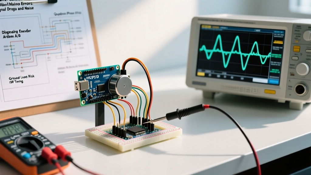
When the serial monitor shows erratic numbers, you need to see the raw electrical signals. A $15 USB logic analyzer (like a 24MHz Saleae clone) is mandatory for this step.
- Probe the Source: Connect the logic analyzer probes as close to the encoder PCB as possible. Verify the A and B channels are clean, 90 degrees out of phase, and reaching full logic levels.
- Probe the MCU: Move the probes to the Arduino GPIO pins. If you see high-frequency ringing or voltage drops that weren't present at the source, you have a signal integrity issue on the PCB or breadboard.
- Trigger on Motor Start: Set the logic analyzer to trigger when the motor PWM pin goes HIGH. Observe the encoder signals at the exact moment the motor energizes. If you see a burst of microsecond glitches on the A/B lines right as the motor starts, your EMI shielding or decoupling is insufficient.
- Sample Rate Rule: Always sample at least 4x to 8x the maximum expected encoder frequency. If your max frequency is 200kHz, set the logic analyzer to 2MHz minimum to accurately capture narrow noise spikes that might trigger the Arduino's attachInterrupt() edge detection.
Expert Troubleshooting FAQ
Why does my encoder work perfectly on a bench power supply but fail when connected to a robot chassis?
This is a classic ground loop and common-mode noise issue. When mounted to a metal chassis, the motor casing may ground through the chassis, while the Arduino grounds through the battery negative. High-current motor transients cause the chassis ground to bounce relative to the battery ground. Use an isolated DC-DC converter for the Arduino logic, or ensure a single-point star grounding topology where the battery negative, motor ground, and MCU ground meet at exactly one physical point.
Can I use software debouncing to fix noisy encoder signals?
No. Software debouncing (ignoring state changes within a 50µs window) is suitable for mechanical push buttons, but it is disastrous for quadrature encoders. Encoders rely on the precise phase relationship of high-frequency edges. Introducing artificial delays or ignoring rapid edges will destroy the quadrature state machine, leading to massive position drift. Rely on hardware RC filters (e.g., 100Ω series resistor + 470pF capacitor to ground) if silicon-level filtering is absent.
My absolute encoder (SPI/I2C) reads correct angles but occasionally jumps 360 degrees. Why?
For absolute magnetic encoders like the AS5048A communicating via SPI, a 360-degree jump usually indicates a bit-flip in the 14-bit data word caused by MISO line noise. Ensure your SPI clock speed is not exceeding the encoder's datasheet maximum (often 10MHz for magnetic sensors). Additionally, add a 10kΩ pull-up resistor on the SPI Chip Select (CS) line to prevent floating CS states during MCU boot-up sequences, which can corrupt the internal shift register of the encoder.