
Upgrading your electronics workbench from an 8-bit Arduino Uno or an ESP8266 to the dual-core powerhouse of the ESP32 is a rite of passage for modern makers. However, this migration is rarely plug-and-play. The physical layout, voltage tolerances, and multiplexed peripheral assignments of the ESP32 DevKit V1 pinout present unique hardware traps that can instantly destroy silicon or cause endless boot loops if misunderstood.
At ElectricalFlux, we see countless makers fry their new microcontrollers by treating them like 5V-tolerant ATmega328P chips. This comprehensive migration guide dissects the ESP32 DevKit V1 pinout from an upgrader's perspective, detailing logic level translation, strapping pin hazards, and real-world power delivery diagnostics.
The Migration Shock: Why Arduino Wiring Fails on the ESP32
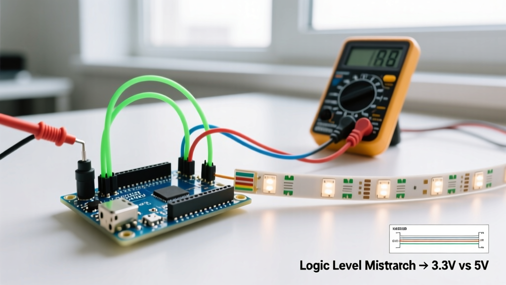
The most critical difference when migrating from an Arduino Uno (ATmega328P) to the ESP32-WROOM-32 module found on the DevKit V1 is the logic voltage. Arduino operates at a robust 5V, whereas the ESP32 is strictly a 3.3V logic device. Feeding a 5V PWM or I2C signal directly into an ESP32 GPIO will degrade the internal ESD protection diodes, eventually leading to a shorted pin or a dead SoC.
Furthermore, the Arduino's forgiving analog pins (A0-A5) map cleanly to the ADC. The ESP32, however, features two distinct Analog-to-Digital converters (ADC1 and ADC2) with severe operational caveats that require immediate code and wiring adjustments during your upgrade.
Decoding the ESP32 DevKit V1 Pinout: A Hardware Upgrader's Map
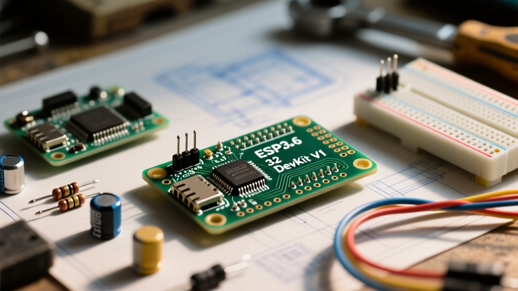
The standard DOIT ESP32 DevKit V1 features a 30-pin layout (15 pins per side). While some cheap clones omit the top GPIOs to save manufacturing costs, a genuine board exposes the following critical zones:
1. The Input-Only Zone (GPIO 34, 35, 36, 39)
Unlike the Arduino, where any digital pin can be toggled HIGH or LOW, GPIOs 34 through 39 on the ESP32 are input-only. They lack internal pull-up or pull-down resistors. If you are migrating a button matrix or limit switch circuit, you must add external 10kΩ pull-up resistors to the 3.3V rail, or your readings will float unpredictably.
2. The Danger Zone: Strapping Pins Explained
When migrating, you must avoid using specific pins for outputs or inputs with external pull-ups during boot. The ESP32 uses 'strapping pins' to determine boot modes and flash voltages. According to the official Espressif ESP32 Datasheet, mishandling these guarantees failure:
- GPIO 0: Determines boot mode. Must be HIGH for normal execution, LOW for flash mode. Do not attach external pull-downs.
- GPIO 2: Must be LOW or floating to enter the serial bootloader. Often problematic if you wire an LED or relay here that pulls it HIGH on startup.
- GPIO 12 (MTDI): The ultimate migration trap. If pulled HIGH at boot, the internal flash voltage regulator switches to 1.8V instead of 3.3V. Since most WROOM-32 modules use 3.3V SPI flash, the board will brownout and boot-loop endlessly.
- GPIO 15: Configures boot log output. Best left floating for standard operations.
Pro-Tip for Upgraders: Never use GPIO 12 for a relay or a switch with a pull-up resistor. If your project requires a reset-safe pin, migrate to GPIO 25, 26, or 27 instead.
5V to 3.3V Logic Level Translation: Upgrading Without Frying Silicon
To safely migrate 5V sensors (like the classic HC-SR04 ultrasonic sensor or 5V I2C LCDs) to the ESP32 DevKit V1, you must step down the voltage. While a simple resistor voltage divider works for slow UART or basic GPIO toggles, it fails miserably for high-speed I2C or SPI buses due to capacitance and rise-time degradation.
| Component | Best For | Speed / Bandwidth | Migration Verdict |
|---|---|---|---|
| Resistor Divider (e.g., 2kΩ/3.3kΩ) | Slow UART, Trigger Pins | Very Low (<10kHz) | Good for HC-SR04 echo pins. Fails on I2C. |
| CD4050B (Non-inverting Buffer) | One-way SPI, SD Cards | Medium (Up to 2MHz) | Excellent, cheap, and reliable for 5V to 3.3V step-down. |
| TXB0108E (Bi-directional) | I2C, SPI, GPIO matrices | High (Up to 50Mbps) | The gold standard. Auto-senses direction. Required for complex bus migrations. |
| BSS138 MOSFET Circuit | I2C Pull-up buses | Medium (Up to 400kHz) | Standard for I2C level shifting. Used on most SparkFun/Adafruit breakout boards. |
For a deeper dive into the physics of logic thresholds, the SparkFun Logic Levels Tutorial provides excellent oscilloscope captures showing why resistor dividers ruin I2C rise times.
Peripheral Mapping: Translating Arduino IDE Code to ESP32
When you open the Arduino IDE to port your sketch, the hardware abstraction layer (HAL) hides some of the ESP32's complexity, but not all of it. The Random Nerd Tutorials ESP32 Pinout Guide highlights the default mappings you must update in your code:
I2C Bus Migration
On an Arduino Uno, I2C is hardwired to A4 (SDA) and A5 (SCL). On the ESP32 DevKit V1, the default I2C pins are GPIO 21 (SDA) and GPIO 22 (SCL). However, the ESP32's GPIO matrix allows you to route I2C to almost any pin. If you are migrating a custom PCB designed for an ATmega, you can force the ESP32 to match your old traces using the Wire library:
Wire.begin(OLD_SDA_PIN, OLD_SCL_PIN);
The ADC2 and WiFi Conflict
This is the most common software-hardware collision during an upgrade. The ESP32 has two ADCs. ADC1 (GPIO 32-39) operates normally. ADC2 (GPIO 0, 2, 4, 12, 13, 14, 15, 25, 26, 27) is completely disabled when the WiFi radio is active. If your legacy Arduino code uses an analog sensor on a pin that maps to ADC2, and your new ESP32 sketch connects to WiFi to upload data, your analog reads will return garbage or fail entirely. Always migrate analog sensors to ADC1 pins (e.g., GPIO 34, 35, 36) before initializing WiFi.begin().
Real-World Migration Failure Modes and Power Diagnostics
The ESP32 DevKit V1 is notorious for power-related brownouts during the upgrade process, specifically when makers transition from low-power Arduino sensors to high-draw WiFi transmissions.
The AMS1117 Voltage Regulator Bottleneck
Most DevKit V1 boards utilize an AMS1117-3.3 linear voltage regulator. This component has a dropout voltage of roughly 1.1V to 1.3V. If you power the board via the 5V USB pin from a weak laptop hub or a long, thin USB cable, the voltage at the regulator input might drop to 4.2V. The regulator will then output an unstable 2.9V, causing the ESP32 to reset the moment the WiFi PA (Power Amplifier) demands its peak current of 240mA to 300mA.
Oscilloscope Diagnostics and the Capacitor Fix
If you hook an oscilloscope to the 3.3V rail of a DevKit V1 during a WiFi beacon transmission, you will often see voltage droops of 400mV to 600mV. To stabilize your migrated project:
- Solder a 100µF Tantalum capacitor and a 0.1µF Ceramic capacitor in parallel directly across the 3.3V and GND pins on the DevKit V1 header.
- Power the board via the
VINpin with a dedicated 5V 2A buck converter rather than relying on the micro-USB port's internal polyfuse, which often trips or introduces resistance.
Sourcing Authentic DevKit V1 Boards in the Clone Market
As of current market conditions, a genuine DOIT or Espressif-branded ESP32 DevKit V1 costs between $8.00 and $11.00. Generic clones from overseas marketplaces sell for $3.50 to $4.50. While clones are fine for breadboarding, they frequently substitute the AMS1117 with cheaper, lower-current LDOs like the ME6211, and they often use the CH340 USB-to-UART chip instead of the CP2102. If your migration project involves industrial environments or continuous 24/7 WiFi operation, invest in the genuine boards with high-quality shielded WROOM-32D modules to ensure the RF trace impedance remains intact.
Final Migration Checklist
- Verify no 5V signals are connected directly to GPIOs.
- Ensure GPIO 12 is not pulled HIGH during boot.
- Move all analog sensors to ADC1 pins if WiFi is enabled.
- Add external pull-ups to input-only pins (GPIO 34-39).
- Bulk decouple the 3.3V rail to handle WiFi TX current spikes.
By respecting the electrical realities of the ESP32 DevKit V1 pinout, your migration from the Arduino ecosystem will result in a vastly superior, IoT-ready project without the silicon casualties.