
The Hardware Layer: Wiring and Pinout Pitfalls
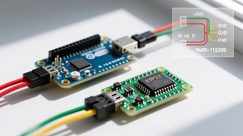
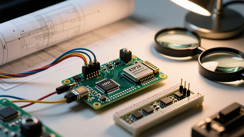
Transitioning from analog microphones (like the MAX9814) to digital I2S MEMS microphones (such as the INMP441 or SPH0645LM4H) is a rite of passage for ESP32 audio projects. However, I2S is an unforgiving protocol. Unlike analog signals that degrade gracefully, I2S timing and pinout errors result in absolute silence or deafening white noise. Before diving into software, we must eliminate hardware configuration errors.
L/R (WS) Pin Configuration: The Silent Killer
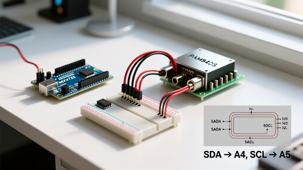
The most frequent cause of 'no audio' on the INMP441 is a mismatch between the hardware L/R pad and the ESP-IDF i2s_channel_fmt_t configuration. The L/R pin dictates which I2S channel the microphone transmits on:
- L/R tied to GND: Microphone outputs on the Left channel.
- L/R tied to VDD (3.3V): Microphone outputs on the Right channel.
If your Arduino sketch or ESP-IDF code configures the I2S peripheral to I2S_CHANNEL_FMT_ONLY_LEFT, but your L/R pad is soldered to VDD, the ESP32 will listen to an empty channel while the microphone transmits on the ignored right channel. Always verify your physical solder jumper against your software struct.
Power Supply Decoupling and RF Interference
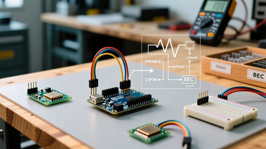
MEMS microphones are incredibly sensitive to power rail noise. The ESP32 is notorious for transient current spikes exceeding 300mA when the WiFi or Bluetooth radios transmit at 2.4GHz. This causes high-frequency voltage sag on the 3.3V LDO, which the microphone interprets as audio data, resulting in a rhythmic 'buzz' or high-frequency whine.
Expert Fix: Do not rely on the ESP32 dev board's onboard capacitors. Solder a 100nF (0.1µF) X7R ceramic capacitor and a 10µF tantalum capacitor directly across the VDD and GND pins of the microphone module, keeping the leads as short as physically possible.
I2S Configuration & The SPH0645 24-Bit Shift Bug
If you are using the incredibly popular SPH0645LM4H-B breakout board, you will likely encounter severe audio distortion or halved amplitude. This is not a software bug on your end; it is a documented hardware timing quirk of the SPH0645 chip itself.
Understanding the Timing Violation
The SPH0645 outputs 24-bit audio data but shifts the data out one bit-clock early compared to the standard Philips I2S specification. When the ESP32 I2S peripheral samples the bus, it captures the data misaligned by one bit. The result is that the audio amplitude is effectively halved, and the 24-bit sign extension is broken, leading to heavy clipping and static.
| Parameter | INMP441 (Standard I2S) | SPH0645LM4H (Shifted I2S) |
|---|---|---|
| I2S Standard | I2S_COMM_FORMAT_STAND_I2S | I2S_COMM_FORMAT_STAND_I2S (Requires SW Fix) |
| Bit Depth | 24-bit (in 32-bit word) | 24-bit (Shifted left by 1) |
| Software Workaround | None required | Bitwise shift right by 1 |
| Sample Rate | 16kHz - 44.1kHz | 16kHz - 22.05kHz (Struggles at 44.1k) |
Implementing the Software Bit-Shift Fix
To correct the SPH0645 data alignment, you must read the DMA buffer into a 32-bit signed integer array and perform a bitwise arithmetic shift. According to the ESP-IDF I2S API Reference, manipulating the buffer post-read is the most stable approach across different ESP32 silicon revisions.
int32_t samples[BUFFER_LEN];
size_t bytes_read;

i2s_read(I2S_PORT, samples, BUFFER_LEN * sizeof(int32_t), &bytes_read, portMAX_DELAY);

for (int i = 0; i < BUFFER_LEN; i++) {
    // Shift right by 1 to fix the SPH0645 timing bug
    // Mask to 24-bit to ensure proper sign handling if required by your DSP
    samples[i] = samples[i] >> 1;
}
DMA Buffer Underruns and RTOS Task Jitter
If your audio recording features random 'clicks', 'pops', or dropped frames, you are experiencing DMA (Direct Memory Access) buffer underruns. The ESP32 uses a dual-core architecture, and the FreeRTOS scheduler can preempt your audio task to handle WiFi interrupts, causing the I2S peripheral to starve.
Optimizing DMA Buffer Sizing
The i2s_config_t struct requires careful tuning of dma_buf_count and dma_buf_len. Setting these too low leaves no margin for RTOS jitter. Setting them too high introduces latency and consumes precious SRAM.
- For Voice Recognition (16kHz): Use
dma_buf_count = 4anddma_buf_len = 256. - For High-Fidelity Streaming (44.1kHz): Use
dma_buf_count = 8anddma_buf_len = 512.
Core Pinning for Audio Tasks
The ESP32 routes WiFi and Bluetooth interrupts to Core 0. If your I2S read loop runs on Core 0, RF interrupts will delay DMA servicing. You must pin your audio processing task to Core 1 using xTaskCreatePinnedToCore. This physical separation guarantees that the I2S DMA controller receives uninterrupted CPU cycles, completely eliminating RTOS-induced audio pops.
Signal Processing: Eliminating DC Offset and Rumble
Even with perfect hardware and I2S timing, MEMS microphones inherently output a DC bias (DC offset). If you feed this raw signal into an FFT or an audio amplifier, the DC offset will cause clipping and ruin low-frequency performance. The Adafruit I2S MEMS Microphone Guide highlights that software high-pass filtering is mandatory for professional results.
Implementing an IIR High-Pass Filter
Rather than using a computationally expensive FIR filter, implement a simple first-order Infinite Impulse Response (IIR) high-pass filter. This removes the DC bias while preserving the AC audio signal with minimal CPU overhead.
float alpha = 0.95; // Cutoff frequency coefficient (closer to 1.0 = lower cutoff)
float prev_in = 0.0;
float prev_out = 0.0;

for (int i = 0; i < BUFFER_LEN; i++) {
    float current_in = (float)samples[i];
    float current_out = alpha * (prev_out + current_in - prev_in);

    samples[i] = (int32_t)current_out;

    prev_in = current_in;
    prev_out = current_out;
}
Master Diagnostic Checklist
When your ESP32 microphone setup fails, run through this exact sequence to isolate the fault domain:
- Oscilloscope/Logic Analyzer Check: Probe the BCLK and WS pins. BCLK should be exactly
Sample Rate × Bit Depth × 2. For 16kHz/24-bit stereo, BCLK must be exactly 768kHz. - Mute Pin Verification: Ensure the L/R pin is not floating. A floating L/R pin causes the microphone to randomly switch channels mid-transmission, corrupting the I2S frame.
- Buffer Dump: Print the first 50 raw 32-bit integers to the serial monitor. If they are all exactly
0or-1, you have a wiring or MISO (SD) line failure. If they are random noise centered around zero, your I2S is working, but your DSP/gain is wrong. - Power Rail Check: Measure the 3.3V rail with an oscilloscope set to AC coupling. If you see 2.4GHz ripple exceeding 30mV, your decoupling capacitors are insufficient or placed too far from the module.
Troubleshooting I2S audio on the ESP32 requires a methodical approach bridging hardware physics and RTOS software architecture. By addressing the SPH0645 timing bug, isolating RTOS tasks, and properly decoupling the power rail, you can achieve studio-grade audio capture from these inexpensive MEMS modules. For deeper peripheral configurations, always consult the official Espressif Sensor and Microphone Documentation.