
The Physics of Strain Gauges and the Wheatstone Bridge
When building a custom weighing scale, force-feedback robot arm, or automated pet feeder, the load cell Arduino combination is the gold standard for precise force measurement. Unlike simple analog sensors like potentiometers or flex resistors, load cells rely on the piezoresistive effect. A typical aluminum straight-bar load cell (ranging from 1kg to 50kg) contains four foil strain gauges bonded to the metal substrate. These gauges are wired in a Wheatstone bridge configuration.
When mechanical force is applied, the substrate bends microscopically. Two strain gauges compress while the other two stretch, causing minute shifts in electrical resistance. Because the excitation voltage (typically 5V) is applied across the bridge, this resistance change outputs a differential voltage in the microvolt (µV) range. For a 2mV/V load cell powered at 5V, a full-scale load might only produce a 10mV signal. This is where the standard Arduino hardware falls short and requires specialized amplification.
Why the Arduino Needs the HX711 24-Bit ADC
The standard Arduino Uno features a 10-bit Analog-to-Digital Converter (ADC), which maps the 0-5V range to 1024 discrete steps (roughly 4.88mV per step). Since your load cell's maximum output might only be 10mV, the Arduino's native ADC would only yield 2 or 3 usable data points across the entire weight range, rendering it entirely useless for precision weighing.
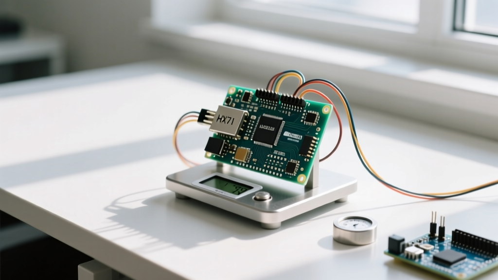
Enter the HX711 amplifier module. This dedicated 24-bit ADC is designed specifically for bridge sensors. It amplifies the microvolt signal and converts it into a high-resolution digital stream. The HX711 features two input channels:
- Channel A: Configurable for a gain of 128 or 64. This is the primary channel used for load cells.
- Channel B: Fixed at a gain of 32. Often used for secondary sensors or battery voltage monitoring in portable scales.
Furthermore, the HX711's sampling rate is controlled by the RATE pin. Tying the RATE pin to GND yields 10 Samples Per Second (SPS), which is ideal for stable, high-noise-rejection weighing. Pulling it to VCC increases the rate to 80 SPS, useful for dynamic force profiling but more susceptible to electrical noise.
Precision Wiring: Pinout and Connections
Wiring a load cell to the HX711, and subsequently to the Arduino, requires attention to the color-coded wires. While colors can occasionally vary by manufacturer (especially with S-type or button load cells), the standard straight-bar color code is highly consistent. Always verify with your specific datasheet if available.
| Load Cell Wire | Standard Color | HX711 Pin | Electrical Function |
|---|---|---|---|
| Excitation+ | Red | E+ | Positive bridge power (matches AVCC) |
| Excitation- | Black | E- | Negative bridge power (Ground) |
| Signal+ | White | A+ | Positive differential signal output |
| Signal- | Green | A- | Negative differential signal output |
| Shield (Optional) | Bare/Yellow | GND | EMI shielding (tie to ground at one end only) |
Note: The HX711 communicates via a proprietary two-wire serial protocol, not standard I2C or SPI. You only need the DT (Data) and SCK (Clock) pins connected to any two digital GPIO pins on your Arduino.
The Non-Blocking Software Approach
Historically, makers used the original Bogde HX711 library. However, that library uses blocking while() loops to wait for the ADC to signal that data is ready. On an Arduino Uno, this might cause a slight stutter. On an ESP32 or WiFi-enabled Arduino, a blocking loop of 100ms can cause the WiFi stack to drop packets or trigger the watchdog timer.
For modern, production-ready projects, we highly recommend the HX711_ADC library by Olof Kraemer. It utilizes a non-blocking state machine, allowing your microcontroller to handle displays, network requests, and button inputs simultaneously while waiting for the 10 SPS data updates.
Calculating the Calibration Factor
The HX711 does not output grams or kilograms; it outputs raw 24-bit integers (ranging roughly from -8,388,608 to 8,388,607). To convert these raw ADC values into meaningful weight units, you must calculate a Calibration Factor.
Pro-Tip: Never guess the calibration factor based on internet forums. Every load cell has manufacturing tolerances, and the HX711's internal voltage reference varies slightly between batches. You must calibrate your exact hardware pair.
The Calibration Routine:
- Upload the calibration sketch with the factor set to
1.0. - Ensure the scale is empty and press 'T' in the Serial Monitor to Tare (zero) the scale.
- Place a precisely known weight on the scale (e.g., a 1000g calibration weight, or a sealed 1kg bag of granulated sugar).
- Record the stabilized raw reading displayed on the serial monitor (e.g., -425,000).
- Calculate the factor:
Calibration Factor = Raw Reading / Known Weight. In this case:-425000 / 1000 = -425.0. - Update your final sketch with this exact factor.
The Final Measurement Sketch
Below is a robust, non-blocking sketch utilizing the HX711_ADC library. It includes a moving average filter concept inherently handled by the library's sampling buffer, which smooths out high-frequency electrical noise.
#include <HX711_ADC.h>

const int HX711_dout = 4; // MCU pin connected to HX711 DT
const int HX711_sck = 5;  // MCU pin connected to HX711 SCK

HX711_ADC LoadCell(HX711_dout, HX711_sck);

const int calVal_eepromAdress = 0;
unsigned long t = 0;

void setup() {
  Serial.begin(57600);
  delay(10);
  Serial.println("Starting...");

  LoadCell.begin();
  LoadCell.start(2000, true); // Stabilize for 2 seconds, ignore anomalies

  if (LoadCell.getTareTimeoutFlag()) {
    Serial.println("Timeout, check wiring!");
    while(1);
  }

  // Replace with your calculated factor from the calibration step
  LoadCell.setCalFactor(-425.0);
  Serial.println("Scale is ready. Tare complete.");
}

void loop() {
  static boolean newDataReady = 0;

  // Non-blocking data check
  if (LoadCell.update()) {
    newDataReady = true;
  }

  if (newDataReady) {
    if (millis() > t + 250) { // Update display at 4Hz
      float weight = LoadCell.getData();
      Serial.print("Weight (g): ");
      Serial.println(weight);
      newDataReady = false;
      t = millis();
    }
  }

  // Handle Serial commands for on-the-fly Tare
  if (Serial.available() > 0) {
    char inByte = Serial.read();
    if (inByte == 't') {
      LoadCell.tareNoDelay();
      Serial.println("Tare initiated...");
    }
  }

  // Check for tare operation complete
  if (LoadCell.getTareStatus()) {
    Serial.println("Tare complete.");
  }
}
Advanced Troubleshooting: Creep, Drift, and EMI
Even with perfect code, physical and electrical anomalies can plague a load cell Arduino setup. Understanding these failure modes separates hobbyists from professional instrumentation engineers.
1. Thermal EMF and Solder Joints
When you solder the HX711 pins, you create dissimilar metal junctions (copper to tin/lead or tin/silver). These act as microscopic thermocouples. If the HX711 board heats up unevenly (e.g., placed near a voltage regulator or in direct sunlight), Thermal Electromotive Force (EMF) generates microvolt errors that the 24-bit ADC will faithfully amplify as phantom weight changes. Solution: Keep the HX711 away from heat sources and allow the enclosure to reach thermal equilibrium before calibration.
2. Mechanical Creep
Creep is a mechanical phenomenon where the load cell's metal substrate slowly deforms over time under a constant load. If you leave a 10kg weight on a 20kg load cell for an hour, the reading might slowly drift downward by 10-50 grams. This is an inherent property of the aluminum alloy. Solution: Implement a software 'tare-on-wake' routine and avoid using the scale for long-term static load monitoring without periodic recalibration.
3. Electromagnetic Interference (EMI)
The wires connecting the load cell to the HX711 act as antennas for high-frequency noise, especially from switching power supplies, LED drivers, or AC motors. Because the signal is in the microvolt range, even minor EMI causes massive jitter. Solution: Use shielded twisted-pair cable for the load cell wires. Connect the shield to the Arduino GND at one end only to prevent ground loops. For further noise rejection, refer to the SparkFun HX711 Hookup Guide for details on adding a 100nF decoupling capacitor directly across the HX711 VCC and GND pins.
By respecting the physics of the Wheatstone bridge, utilizing non-blocking software architectures, and mitigating thermal and electrical noise, your load cell Arduino project will achieve laboratory-grade reliability.