
The Shift to Solid-State Interfaces in 2026
As IoT devices and industrial controllers demand higher ingress protection (IP67 and above), mechanical switches are rapidly being replaced by solid-state interfaces. For makers and engineers, mastering Arduino capacitive touch is no longer optional—it is a fundamental requirement for modern, sealed enclosures. However, many legacy projects still rely on outdated, resistor-based polling methods that fail in high-EMI environments or suffer from severe latency.
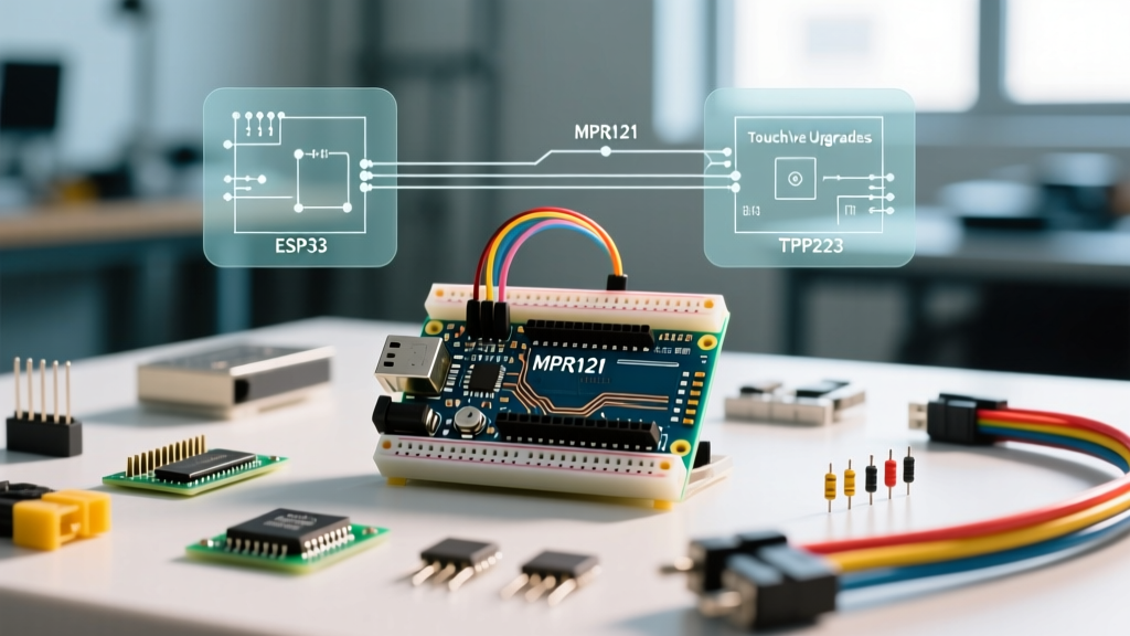
This migration guide provides a comprehensive roadmap for upgrading your capacitive touch implementations. We will transition from the legacy CapacitiveSensor library approach to dedicated hardware ICs like the MPR121 and TTP223, as well as native SoC peripherals found in the ESP32 family.
The Legacy Baseline: The CapacitiveSensor Library
For over a decade, the standard approach for Arduino capacitive touch involved the CapacitiveSensor library. This method uses a high-value resistor (typically 1MΩ to 10MΩ) between a send pin and a receive pin. The microcontroller measures the RC time constant required to charge the parasitic capacitance of the electrode and the user's finger.
Why You Need to Migrate Away
- Blocking Code: The library relies on tight polling loops (
capacitiveSensorRaw()), which blocks the main thread and starves RTOS tasks or fast-refresh displays. - EMI Susceptibility: Without dedicated analog front-end (AFE) filtering, 50Hz/60Hz mains hum and switching power supply (SMPS) noise cause massive baseline drift.
- Environmental Drift: Humidity and temperature changes alter the dielectric constant of the PCB substrate, leading to false triggers or dead zones.
Migration Path 1: TTP223 (The Single-Channel Quick Fix)
If your project only requires 1 to 4 discrete buttons and you are constrained by budget and board space, the TTP223 is the ideal drop-in upgrade. Priced at roughly $0.15 per module in 2026, this single-channel IC handles the RC oscillation internally and outputs a clean digital HIGH/LOW signal.
Upgrade Advantage: You eliminate the 10MΩ resistor and the blocking polling code. The TTP223 handles auto-calibration and environmental drift compensation in hardware, freeing your MCU to handle core logic or drive WS2812B LED arrays without timing interruptions.
Migration Path 2: MPR121 (The 12-Channel Professional Standard)
For complex UIs, slider controls, or multi-touch keypads, the NXP MPR121 remains the gold standard for Arduino migrations. According to the NXP MPR121 Datasheet, this IC features 12 independent capacitive sensing inputs with built-in auto-calibration, debounce filtering, and out-of-range (OOR) detection.
Key Hardware Features for Migration
- I2C Interface: Operates at up to 400kHz, requiring only two MCU pins (SDA/SCL) plus an optional interrupt (IRQ) line.
- Proximity Detection: Can detect a hand approaching from up to 10cm away, allowing you to wake a display before the user actually touches the interface.
- LED Driving: Unused touch pins can be repurposed as PWM LED drivers, reducing the total BOM (Bill of Materials) cost.
Expert Tip: When migrating to the MPR121, do not ignore the ELE_CFG register (0x5E). The IC remains in a stopped state by default. You must write the number of enabled electrodes to this register to activate the sensing engine.
Migration Path 3: Native ESP32 Touch Peripherals
If your migration involves moving from an 8-bit AVR (like the ATmega328P) to a 32-bit architecture, the ESP32-WROOM-32 offers 10 built-in capacitive touch GPIOs. As detailed in the Espressif Touch Sensor API Documentation, these pins are connected to an internal RTC hardware subsystem.
The Killer Feature: Because the touch controller is tied to the Real-Time Clock (RTC) domain, it can trigger an interrupt to wake the ESP32 from ultra-low-power deep sleep (drawing less than 10µA). This is critical for battery-operated field sensors in 2026.
Technical Comparison Matrix
| Feature | Legacy CapacitiveSensor | TTP223 Module | NXP MPR121 | ESP32 Native Touch |
|---|---|---|---|---|
| Cost (Approx.) | $0.05 (Resistor) | $0.15 / channel | $6.00 - $9.00 (Breakout) | $0.00 (Built-in) |
| Max Channels | Limited by MCU pins | 1 per IC | 12 (Up to 8 proximity) | 10 (ESP32 v1) |
| Interface | Direct GPIO Polling | Digital GPIO | I2C (Address 0x5A) | Internal RTC Bus |
| Auto-Calibration | No (Software required) | Yes (Hardware) | Yes (Advanced AFE) | Yes (Firmware API) |
| Deep Sleep Wake | No | No | Yes (via IRQ pin) | Yes (Native RTC) |
PCB & Hardware Layout Rules for Capacitive Migration
Upgrading your silicon is only half the battle. Capacitive sensing is fundamentally an exercise in managing parasitic capacitance ($C_p$) and electromagnetic interference. Follow these strict layout rules when designing your custom PCB or wiring your breakout boards:
1. Trace Routing and Length
Keep the traces from the IC to the touch electrode as short as possible. Ideally, traces should be under 15mm. If you must route longer distances, use a guarded trace (a shield trace driven by a buffered square wave in-phase with the sensing signal) to eliminate the capacitance of the wire itself.
2. The Ground Plane Dilemma
A solid ground plane directly beneath a touch pad will create a massive parasitic capacitor between the pad and the ground plane, drastically reducing sensitivity. The Solution: Use a hatched ground plane (a 45-degree grid with 15% to 20% copper density) under the sensing area. This provides EMI shielding without creating a solid parallel-plate capacitor.
3. Cover Material Thickness
The dielectric material between the electrode and the user's finger dictates the signal-to-noise ratio (SNR).
- Glass (3mm): Excellent SNR, high scratch resistance, but heavy.
- Acrylic/PMMA (2mm - 4mm): Good balance of cost and sensitivity.
- ABS Plastic (Injection Molded): Requires careful tuning of the MPR121's
MHDRandNHDregisters to account for lower dielectric constants.
Step-by-Step Software Migration Flow
Moving from blocking polling code to interrupt-driven I2C requires a shift in software architecture. Here is the standard migration flow for the MPR121:
- Initialize I2C: Set the I2C clock to 400kHz (
Wire.setClock(400000)) to minimize bus occupancy. - Configure AFE Registers: Write to the Max Half Delta (
MHDR), Noise Half Delta (NHD), Noise Count Limit (NCL), and Filter Delay Count Limit (FDL) registers to tune the baseline tracking speed. - Set Touch/Release Thresholds: Define the
TOUandRELregisters. A typical starting point is a touch threshold of 12 and a release threshold of 6 (representing the drop in capacitance count). - Attach Hardware Interrupt: Connect the MPR121 IRQ pin to an MCU interrupt-capable pin (e.g., Pin 2 on an Uno, or GPIO 34 on an ESP32). Configure it for
FALLINGedge. - Read Status in ISR: In the Interrupt Service Routine, read the
TOUCH_STATUSregister (0x00) to determine which pads were triggered, then clear the interrupt flag.
Real-World Edge Cases & Troubleshooting
Even with dedicated ICs, real-world environments introduce complex failure modes. Here is how to handle the most common edge cases encountered in the field:
Water Droplet False Triggers
In kitchen or outdoor environments, water droplets on the cover material can mimic a finger touch. The MPR121 handles this via its Out-Of-Range (OOR) detection. If the capacitance exceeds a logical physical limit (indicating a massive dielectric shift like standing water), the OOR flag is set. Your firmware should be programmed to ignore touch events if the OOR bit in register 0x02 is high.
SMPS Noise and Baseline Drift
Switching Mode Power Supplies operating at 100kHz to 1MHz can inject noise into the ground plane, causing the baseline capacitance to jitter. If you are powering your Arduino via a cheap USB wall-wart, you may see erratic readings. Fix: Add a 100µF low-ESR tantalum capacitor and a 0.1µF ceramic decoupling capacitor as close to the VCC/GND pins of the touch IC as possible. Additionally, ensure your USB cable has a properly terminated shield connected to chassis ground.
ESP32 Threshold Inversions
When migrating to the ESP32, remember that the touch sensor reads *lower* values when touched (capacitance increases, discharge time decreases). This is the inverse of many analog sensors. Ensure your touchAttachInterrupt() threshold logic accounts for this drop (e.g., triggering when the value falls below 40, rather than rising above it).
Conclusion
Upgrading your Arduino capacitive touch implementation from legacy resistor-based polling to dedicated silicon like the MPR121 or native ESP32 peripherals is a mandatory step for any professional-grade project in 2026. By offloading the analog signal processing to dedicated hardware, you eliminate blocking code, drastically improve EMI rejection, and unlock advanced features like deep-sleep waking and proximity detection. Evaluate your channel count, budget, and environmental constraints using the matrix above, and apply strict PCB layout rules to ensure a flawless, solid-state user interface.