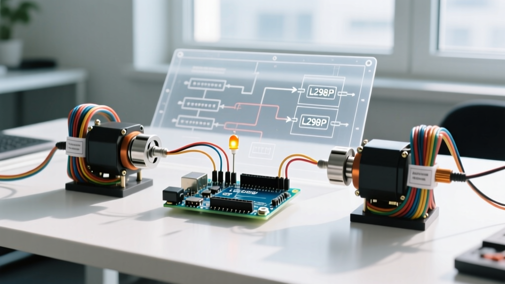

Introduction to the L298P Motor Control Shield
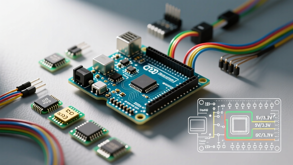
Transitioning from blinking LEDs to moving mechanical parts is a major milestone in any maker's journey. While raw H-bridge ICs require messy breadboard wiring, a dedicated motor control shield for Arduino abstracts the complexity, providing robust screw terminals, integrated flyback diodes, and direct stacking. Among the most ubiquitous and reliable options in 2026 remains the L298P-based shield, popularized by the official Arduino Motor Shield R3 and various DFRobot clones.
Unlike its older through-hole sibling (the L298N), the L298P is a surface-mount IC featuring an exposed thermal pad on the bottom. This design transfers heat directly into the shield's copper ground plane, allowing for slightly higher continuous current limits before thermal shutdown occurs. This tutorial will walk you through the exact wiring, power routing logic, and C++ code required to get your DC motors running smoothly.
Hardware Requirements and Specifications
Before writing code, it is critical to understand the physical limitations and pinout of the shield. Most L298P shields map to the exact same hardware pins, ensuring cross-compatibility between genuine boards (typically $30-$35) and third-party clones ($8-$12).
- Microcontroller: Arduino Uno R3, Uno R4 Minima, or Mega 2560.
- Motor Driver IC: STMicroelectronics L298P Dual Full-Bridge Driver.
- Operating Voltage (Logic): 5V (regulated onboard or via Arduino).
- Operating Voltage (Motor VIN): 5.5V to 12V (absolute max 18V).
- Max Current per Channel: 2A (peak), 1.5A (continuous with adequate cooling).
- Wiring: 18-20 AWG stranded silicone wire for motor terminals to handle >1A loads without voltage sag.
Pinout Mapping
The L298P shield hardwires specific Arduino pins to control Motor A and Motor B. You cannot change these without physically cutting traces on the PCB.
| Function | Motor A Pin | Motor B Pin | Description |
|---|---|---|---|
| Direction | D12 | D13 | HIGH for forward, LOW for reverse. |
| PWM (Speed) | D10 | D11 | Analog write (0-255) for speed control. |
| Brake | D9 | D8 | HIGH engages the dynamic brake (shorts motor coils). |
| Current Sensing | A0 | A1 | Analog read to estimate current draw (approx. 1.65V/A). |
Power Routing: The VIN Jumper Matrix
The most common point of failure for beginners is mismanaging the power routing. The shield features a 2-pin header labeled VIN with a removable jumper. This jumper dictates how the motors and the Arduino receive power.
| Power Mode | Jumper State | Use Case | Risk Level |
|---|---|---|---|
| Single Source | Connected (Default) | Running small 5V-9V motors and powering the Arduino via the shield's DC jack. | Medium (High motor inrush can reset Arduino). |
| Dual Source | Removed (Cut Trace) | Running high-current 12V motors while powering the Arduino via USB or separate battery. | Low (Safest for high-torque applications). |
Critical Warning: If you are using motors that draw more than 500mA at startup, you must remove the VIN jumper and power the Arduino separately. Failing to do so will cause the motor's inrush current to drag the shared voltage rail below 4.5V, triggering a brownout reset on the Arduino's ATmega328P or RA4M1 chip.
Step-by-Step Wiring Guide
- Mount the Shield: Align the female headers of the shield with the male headers of the Arduino Uno. Press down firmly and evenly until the shield sits flush.
- Configure Power: Decide on your power routing. For this tutorial, we will use a dual-source setup. Snip the VIN jumper trace or remove the jumper cap, then connect your Arduino to your PC via USB.
- Connect Motor Power: Strip 6mm of insulation from your 18 AWG motor power wires. Insert them into the green screw terminals labeled
VINandGND. Tighten the screws firmly. A loose connection will cause arcing and melt the terminal block under high current. - Connect the Motors: Attach Motor A to terminals
A+andA-, and Motor B toB+andB-. Polarity does not matter initially; you can swap the wires if the software direction logic is inverted. - Add Bulk Capacitance (Pro-Tip): Solder or screw a 470µF to 1000µF electrolytic capacitor directly across the
VINandGNDmotor terminals. This acts as a local energy reservoir, absorbing inductive voltage spikes and supplying inrush current without dipping the main battery voltage. Learn more about managing motor driver inrush currents in the SparkFun Motor Driver Selection Guide.
Writing the Arduino Sketch
The L298P does not require external libraries like I2C or SPI motor shields. It relies on standard digital and PWM signals. According to the official Arduino analogWrite() documentation, pins 10 and 11 operate at a default PWM frequency of 490Hz, which is ideal for DC motors as it sits above the audible whine threshold while minimizing switching losses in the BJT transistors.
Below is a robust sketch that accelerates Motor A, applies a dynamic brake, and then reverses it.
// Pin Definitions for L298P Shield
const int DIR_A = 12;
const int PWM_A = 10;
const int BRAKE_A = 9;

void setup() {
  pinMode(DIR_A, OUTPUT);
  pinMode(PWM_A, OUTPUT);
  pinMode(BRAKE_A, OUTPUT);

  // Ensure motor is stopped and brake is disengaged on boot
  digitalWrite(BRAKE_A, LOW);
  analogWrite(PWM_A, 0);
}

void loop() {
  // 1. Forward Acceleration
  digitalWrite(DIR_A, HIGH); // Set Forward Direction
  for (int speed = 0; speed <= 255; speed += 5) {
    analogWrite(PWM_A, speed);
    delay(20);
  }

  // 2. Cruise at max speed for 2 seconds
  delay(2000);

  // 3. Engage Dynamic Brake (Stops motor faster than just cutting PWM)
  digitalWrite(BRAKE_A, HIGH);
  analogWrite(PWM_A, 0);       // Cut PWM signal
  delay(1000);                 // Hold brake for 1 second
  digitalWrite(BRAKE_A, LOW);  // Release brake

  // 4. Reverse Direction
  digitalWrite(DIR_A, LOW);    // Set Reverse Direction
  analogWrite(PWM_A, 200);     // Run at ~78% speed in reverse
  delay(2000);

  // 5. Coast to stop
  analogWrite(PWM_A, 0);
  delay(2000);
}
Advanced Troubleshooting and Edge Cases
Even with correct wiring, BJT-based H-bridges present unique physical challenges. Here is how to diagnose the most common issues encountered with the L298P motor control shield for Arduino.
1. The 'Missing Voltage' Phenomenon
If you supply exactly 5V to the motor VIN terminal, your 5V DC motors will likely barely spin. The L298P uses bipolar junction transistors (BJTs) rather than MOSFETs. This architecture introduces a forward voltage drop (Vf) of roughly 1.5V to 2.5V depending on the current draw. Therefore, a 5V input yields only ~3V at the motor terminals. Solution: Always supply 7V to 9V to the shield when driving standard 5V or 6V hobby motors to compensate for the internal drop.
2. Thermal Shutdown at 1.5A
The L298P has a built-in thermal shutdown circuit that triggers at roughly 150°C junction temperature. Because the shield relies on a small stick-on heatsink and PCB copper pour, continuous draws above 1.2A per channel will trigger this protection within 3 to 5 minutes in a stagnant room-temperature environment. If your project requires continuous 2A loads, you must add forced air cooling (a 30mm 5V fan) or upgrade to a modern MOSFET-based shield like the DRV8833 or TB6612FNG.
3. Inductive Kickback and Logic Glitches
While the shield includes onboard 1N4007 flyback diodes to protect the H-bridge from reverse EMF, long motor wires can act as antennas, radiating electromagnetic interference (EMI) back into the Arduino's logic lines. If you notice your Arduino randomly resetting or I2C sensors dropping out when the motor engages, twist your motor wires tightly (1 twist per inch) to cancel the magnetic field, and ensure your motor power ground and logic ground share a single, short star-ground point.
Final Thoughts
Mastering a motor control shield for Arduino requires looking past the software and respecting the physics of power electronics. By understanding the L298P's voltage drop, managing power routing via the VIN jumper, and implementing bulk capacitance, you transform a basic hobby shield into a reliable actuation platform. For deeper technical specifications on the official board layout and schematic, refer to the Arduino Motor Shield R3 Documentation.