
The Ultimate Joystick Arduino Quick-Reference Guide
Integrating a dual-axis analog joystick into an Arduino or ESP32 project is a rite of passage for makers. Whether you are building an RC car transmitter, a camera gimbal controller, or a retro gaming interface, joysticks provide intuitive 2D input. However, beneath the simple 5-pin interface lies a web of analog-to-digital conversion (ADC) quirks, floating pin issues, and carbon-track wear that can derail your project.
This FAQ and quick-reference guide cuts through the fluff. We tackle the exact hardware failure modes, ESP32 non-linearity edge cases, and C++ deadzone implementations you need to build a bulletproof joystick Arduino interface in 2026.
Quick-Reference Pinout Matrix
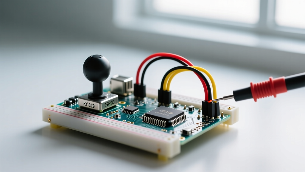
The most common module is the KY-023 (a low-cost clone of the PS2 dual-axis module, typically $1.50 to $3.00). Below is the wiring matrix for standard 5V and 3.3V microcontrollers.
| KY-023 Pin | Arduino Uno / Nano (5V) | ESP32 (3.3V Logic) | Function & Notes |
|---|---|---|---|
| GND | GND | GND | Common ground reference. |
| +5V | 5V | 3.3V (or 5V w/ divider) | Powers the internal 10kΩ potentiometers. |
| VRx | A0 | GPIO34 (ADC1_CH6) | X-Axis analog wiper output. |
| VRy | A1 | GPIO35 (ADC1_CH7) | Y-Axis analog wiper output. |
| SW | D2 | GPIO25 | Momentary button (Active LOW). |
Hardware & Wiring FAQs
Why does my ESP32 clip joystick values at the high end?
This is the most common issue when migrating a joystick Arduino project to an ESP32. The ESP32 utilizes a Successive Approximation Register (SAR) ADC, which is notoriously non-linear at the voltage extremes. When using the default ADC_11db attenuation, the ADC saturates around 3.1V. If you power the joystick with 3.3V, the maximum wiper output (3.3V) will read as a saturated ~4095, but the values between 2.9V and 3.3V will be highly compressed and noisy.
The Fix: Power the KY-023 with 5V, but use a hardware voltage divider on the VRx and VRy pins to scale the 0-5V output down to a safe 0-3.0V range for the ESP32. Use a 2.2kΩ (R1) and 3.3kΩ (R2) resistor pair. The math: Vout = 5V * (3.3k / (2.2k + 3.3k)) = 3.0V. This keeps the signal entirely within the ESP32's linear ADC response curve.
Why does my microcontroller reset or spam serial data when I press the joystick button?
The SW (switch) pin on standard joystick modules is an Active LOW circuit. Internally, pressing the button connects the SW pin directly to GND. However, the module lacks an onboard pull-up resistor. If you configure the pin as a standard INPUT, the pin becomes high-impedance (floating) when the button is released. A floating pin acts as an antenna, picking up 50/60Hz mains noise and ambient EMI, causing erratic serial outputs or false interrupts.
The Fix: Always configure the button pin using the internal pull-up resistor in your setup() function:
pinMode(SW_PIN, INPUT_PULLUP);With this configuration, the pin reads HIGH when idle, and cleanly drops to LOW when pressed.
Software, Code & Calibration FAQs
How do I implement a radial deadzone to stop idle jitter?
Cheap 10kΩ carbon-track potentiometers rarely return exactly 512 (on a 10-bit ADC) when centered. They often rest anywhere between 495 and 525. If you map these raw values directly to motor speeds or servo angles, your project will 'creep' or jitter at idle.
Instead of a simple square deadzone, use a Pythagorean radial deadzone. This calculates the physical distance from the center point, ignoring minor carbon-track variations while preserving the analog curve outside the deadzone.
const int X_PIN = A0;
const int Y_PIN = A1;
const int CENTER_X = 512;
const int CENTER_Y = 512;
const int DEADZONE_RADIUS = 25;

void setup() {
  Serial.begin(115200);
}

void loop() {
  int rawX = analogRead(X_PIN);
  int rawY = analogRead(Y_PIN);

  int deltaX = rawX - CENTER_X;
  int deltaY = rawY - CENTER_Y;

  // Calculate radial distance using Pythagorean theorem
  float distance = sqrt(pow(deltaX, 2) + pow(deltaY, 2));

  if (distance < DEADZONE_RADIUS) {
    Serial.println('Joystick in Deadzone (Idle)');
  } else {
    Serial.print('Active Input - Distance: ');
    Serial.println(distance);
  }
  delay(50);
}
What is the best way to map analog values to servo angles?
The standard Arduino map() function is useful, but applying it directly to a joystick results in hyper-sensitive center movements. For servo control (0-180 degrees), map the raw 0-1023 analogRead() values, but apply a software constraint to prevent mechanical binding at the servo's physical limits.
int rawVal = analogRead(X_PIN);
int servoAngle = map(rawVal, 0, 1023, 10, 170); // Avoid 0 and 180 extremes
servoAngle = constrain(servoAngle, 10, 170);
myServo.write(servoAngle);
Advanced Edge Cases & Component Failure
My joystick physically drifts over time. Is it a code issue?
If your center point slowly shifts from 512 to 450 over a few weeks of use, you are experiencing carbon track wear. The KY-023 and similar modules use physical wipers scraping against a carbon resistive element. These are typically rated for only 10,000 to 30,000 mechanical cycles. Heavy use (like continuous RC steering) literally sands away the carbon, altering the resistance curve and causing permanent hardware drift.
The 2026 Upgrade Path: If your project requires high durability, abandon carbon potentiometers. Upgrade to a Hall-Effect 3D Joystick (such as the Alps Alpine RKJXT1F42001 or generic Hall modules used in modern Xbox Elite controllers, costing roughly $5.00 to $8.00). Hall-effect sensors use magnets and magnetic flux sensors to determine position. Because there is zero physical contact between the sensor and the moving shaft, they offer an effectively infinite mechanical lifecycle and completely eliminate carbon drift.
Can I use multiple joysticks on a single Arduino Uno?
Yes, but you will hit the ADC channel limit quickly. The ATmega328P on the Uno has only 6 analog pins (A0-A5). Two joysticks will consume 4 pins (VRx1, VRy1, VRx2, VRy2). If you need to multiplex more joysticks, use an I2C ADC multiplexer like the Adafruit ADS1115 (16-bit precision, ~$10.95). It provides 4 high-resolution analog inputs over just two I2C wires, freeing up your microcontroller's native pins and offering vastly superior noise rejection compared to the Uno's internal ADC.
Authoritative References
- Arduino Official Documentation: analogRead() and ADC Resolution
- Arduino Official Documentation: map() Math Function Reference
- SparkFun Electronics: Thumb Joystick Breakout (COM-09032) Technical Specs