
Introduction to IR Communication in Microcontrollers
Infrared (IR) communication remains one of the most reliable, cost-effective, and widely used methods for short-range wireless control in DIY electronics. When integrating an IR remote control for Arduino projects, you are leveraging the same 38kHz carrier frequency technology found in commercial television and HVAC systems. Unlike RF (Radio Frequency) or Bluetooth, IR requires line-of-sight but offers zero pairing overhead, making it ideal for instant-on maker projects like motorized blinds, LED strip controllers, and robotic rovers.
However, the landscape of Arduino IR libraries has shifted dramatically in recent years. Many legacy tutorials rely on outdated syntax that will immediately throw compilation errors in modern Arduino IDE 2.x environments. This guide provides a comprehensive, up-to-date walkthrough on hardware selection, modern IRremote v4.x syntax, and advanced troubleshooting for real-world interference.
Hardware Selection: VS1838B vs. TSOP38238
The first step in building a robust IR receiver circuit is choosing the right demodulator. While cheap starter kits flood the market with generic sensors, understanding the difference between standard and premium receivers will save you hours of debugging.
| Feature | VS1838B (Generic Kit Standard) | Vishay TSOP38238 (Premium) |
|---|---|---|
| Typical Price (2026) | $0.15 - $0.30 per unit | $1.20 - $1.80 per unit |
| Carrier Frequency | 38kHz | 38kHz |
| AGC (Automatic Gain Control) | Basic (Prone to saturation) | Advanced (Rejects continuous noise) |
| Max Range | ~8 meters (optimal conditions) | ~35 meters (high-gain remotes) |
| Sunlight Rejection | Poor | Excellent |
Expert Recommendation: If your project will operate outdoors, near windows, or in rooms with modern dimmable LED bulbs, invest in the Vishay TSOP38238. Its internal AGC algorithm specifically filters out the continuous IR noise emitted by fluorescent and PWM-driven LED lighting.
Wiring the IR Receiver to the Arduino
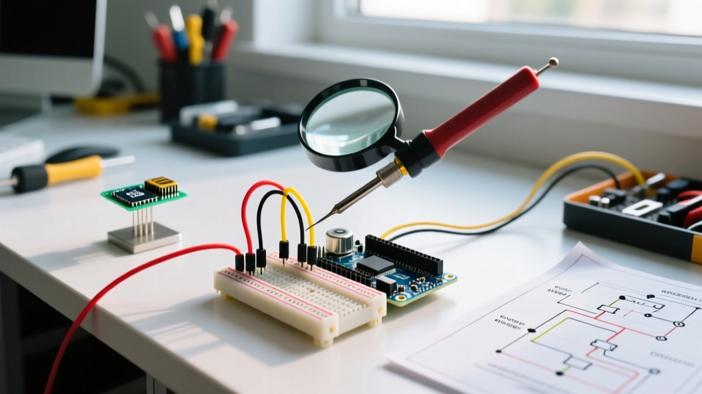
Most IR receiver breakout boards feature three pins: VCC, GND, and OUT (or DAT). While you can plug these directly into a breadboard, professional deployments require power decoupling to prevent voltage sags when the Arduino switches high-current loads (like relays or motors) simultaneously.
Standard Wiring Diagram
- VCC: Connect to Arduino 5V (or 3.3V if using a 3.3V logic board like the ESP32, though the TSOP38238 supports 2.5V to 5.5V).
- GND: Connect to Arduino GND.
- OUT: Connect to Digital Pin 11 (default for most examples, but any digital pin works).
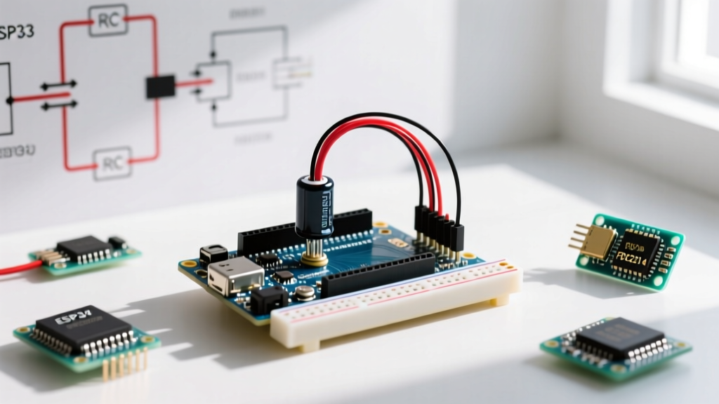
Pro-Tip (Power Decoupling): Place a 100Ω resistor in series with the VCC line, and a 4.7µF electrolytic capacitor between VCC and GND directly at the receiver pins. This creates a low-pass filter that protects the receiver's sensitive internal pre-amplifier from voltage spikes generated by inductive loads on your breadboard.
Software Setup: Navigating the IRremote v4.x Shift
The most common failure mode for beginners in 2026 is copying code from tutorials written before 2021. The Arduino-IRremote library underwent a massive architectural rewrite in versions 3.0 and 4.0. The old irrecv.decode(&results) syntax has been entirely deprecated.
To install the correct library:
- Open Arduino IDE 2.x and navigate to Sketch > Include Library > Manage Libraries.
- Search for IRremote by shirriff, z3t0, and ArminJo.
- Install the latest 4.x version.
Step 1: Decoding Your Remote's Hex Codes
Before mapping buttons to actions, you must sniff the hex codes your specific remote transmits. Most inexpensive 24-key remotes use the NEC Protocol, which transmits a 32-bit data frame consisting of an address and a command.
#include <IRremote.h>

// Define the pin connected to the IR receiver OUT
const int RECV_PIN = 11;

void setup() {
  Serial.begin(9600);
  // Initialize the IR receiver (v4.x syntax)
  IrReceiver.begin(RECV_PIN, ENABLE_LED_FEEDBACK);
  Serial.println("IR Receiver Ready. Point remote and press buttons.");
}

void loop() {
  if (IrReceiver.decode()) {
    // Print the protocol, hex value, and bit length
    Serial.print("Protocol: ");
    Serial.print(IrReceiver.decodedIRData.protocol);
    Serial.print(" | Hex Value: 0x");
    Serial.print(IrReceiver.decodedIRData.decodedRawData, HEX);
    Serial.print(" | Bits: ");
    Serial.println(IrReceiver.decodedIRData.numberOfBits);

    // Crucial: Resume receiving after a successful decode
    IrReceiver.resume();
  }
}
Step 2: Mapping Codes to Actions
Once you have recorded the hex values for your remote's buttons (e.g., Power = 0xFFA25D, Vol+ = 0xFFE01F), you can implement a switch statement. Note that in v4.x, the decoded hex data is stored in IrReceiver.decodedIRData.decodedRawData (or command for cleaner NEC parsing).
void loop() {
  if (IrReceiver.decode()) {
    uint32_t command = IrReceiver.decodedIRData.command;

    switch (command) {
      case 0x18: // Example NEC command for '1'
        Serial.println("Button 1 Pressed - Activating Relay");
        digitalWrite(RELAY_PIN, HIGH);
        break;

      case 0x5A: // Example NEC command for '2'
        Serial.println("Button 2 Pressed - Deactivating Relay");
        digitalWrite(RELAY_PIN, LOW);
        break;

      default:
        Serial.print("Unknown Command: 0x");
        Serial.println(command, HEX);
    }
    IrReceiver.resume();
  }
}
Real-World Troubleshooting and Edge Cases
Even with perfect wiring, IR systems are susceptible to environmental physics. Here is how to diagnose and fix the most common edge cases encountered in the field.
1. The 'Phantom Button' Presses (Interference)
Symptom: The Serial Monitor prints random hex codes or UNKNOWN protocols without you touching the remote.
Cause: Modern LED bulbs with PWM dimmers, CFL bulbs, and direct sunlight emit broadband infrared noise that saturates the receiver's photodiode.
Fix: Switch to a Vishay TSOP38238 receiver. If you must use a generic VS1838B, physically shield the sensor with a dark, IR-transparent acrylic filter (often salvaged from old VCRs or DVD players) and move the sensor away from overhead lighting.
2. Repeat Codes Returning as 0xFFFFFFFF
Symptom: Holding down a button outputs the correct hex code once, followed by a stream of 0xFFFFFFFF.
Cause: This is not a bug; it is a feature of the NEC protocol. The 0xFFFFFFFF is a dedicated 'Repeat Frame' sent every 108ms to indicate the button is still held down.
Fix: Add a simple boolean flag or ignore statement in your code to filter out repeat frames if your application only requires single-trigger events.
3. Compilation Errors: 'IRrecv' does not name a type
Symptom: Code fails to compile with errors referencing irrecv or decode_results.
Cause: You are using v2.x syntax with the v4.x library installed.
Fix: Replace IRrecv irrecv(RECV_PIN); with the modern IrReceiver.begin() initialization shown in the code blocks above. The global IrReceiver object is instantiated automatically by the modern library header.
Frequently Asked Questions
Can I use an IR remote and an IR LED transmitter on the same Arduino?
Yes. The IRremote library supports simultaneous sending and receiving. However, you must ensure the IR transmitter LED is driven by a transistor (like a 2N2222 or MOSFET) rather than directly from an Arduino GPIO pin, which maxes out at 20mA-40mA. An IR LED typically requires 100mA+ pulses for adequate range.
Why does my remote only work from 2 feet away?
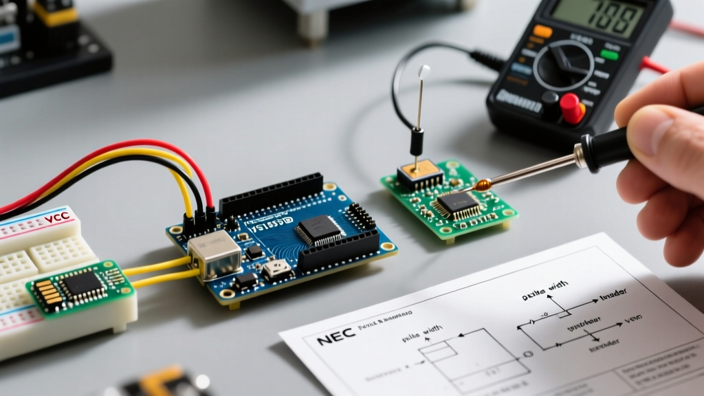
Range issues are almost always tied to power delivery. If you are powering the Arduino via USB from a low-quality wall adapter, the 5V rail may be sagging to 4.2V under load, severely reducing the receiver's sensitivity. Measure the VCC pin with a multimeter while pressing remote buttons; if it drops below 4.5V, upgrade your power supply or add the decoupling capacitor mentioned earlier.
Do all TV remotes work with Arduino?
Most standard TV remotes use the NEC, RC5, or RC6 protocols, all of which are fully supported by the IRremote library. However, some modern smart TV remotes use Bluetooth Low Energy (BLE) or RF for voice commands and advanced navigation. The physical IR blaster on those remotes usually only handles basic power and volume commands, which the Arduino can still decode perfectly.