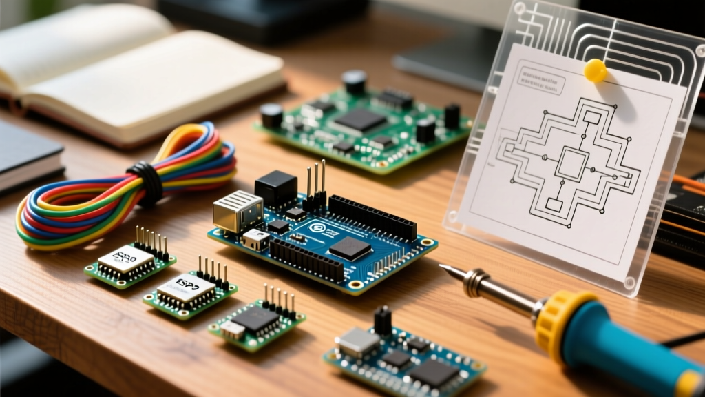

Introduction to DIY Engine Management
Building a custom engine control unit (ECU) from scratch was once a task reserved for automotive engineers with access to proprietary software and expensive hardware. Today, the open-source maker community has democratized engine management. By leveraging an Arduino ECU architecture, enthusiasts can run sophisticated fuel and ignition maps using platforms like Speeduino or RusEFI. However, an engine bay is a brutal environment characterized by extreme temperature swings, high-voltage inductive spikes, and severe electromagnetic interference (EMI).
Selecting the right microcontroller, sensor conditioning circuits, and output drivers is not just a matter of making the code compile; it is a matter of preventing catastrophic engine failure. This compatibility guide breaks down the exact hardware pairings, impedance requirements, and signal conditioning necessary to build a reliable Arduino-based ECU in 2026.
Microcontroller Board Compatibility Matrix
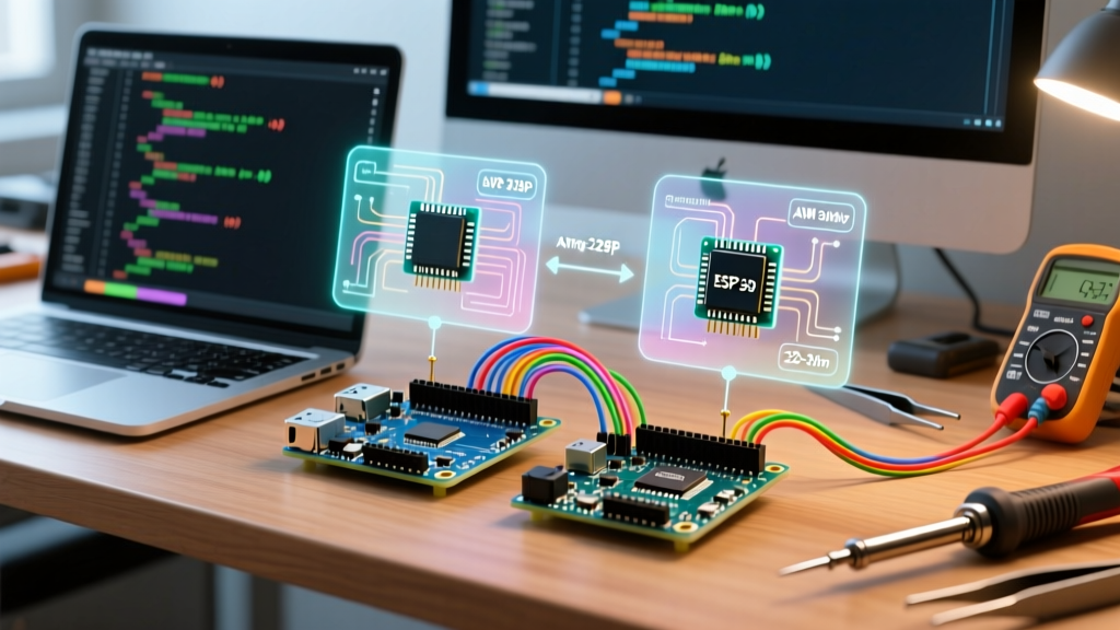
Not all 'Arduino' boards are created equal when it comes to real-time engine calculations. Calculating volumetric efficiency (VE), applying temperature corrections, and firing injectors at 7,000 RPM requires precise interrupt handling and fast floating-point math. Below is a compatibility matrix for the most common MCU boards used in DIY ECU projects.
| Microcontroller Board | Core Processor | Clock Speed | Best Use Case | Compatible Firmware |
|---|---|---|---|---|
| Arduino Mega 2560 | ATmega2560 (8-bit AVR) | 16 MHz | Batch fire, up to 4-cyl sequential | Speeduino |
| Teensy 4.1 | ARM Cortex-M7 (32-bit) | 600 MHz | 8+ cyl sequential, high-RPM, VVT | Speeduino, RusEFI |
| STM32F407 'Black Pill' | ARM Cortex-M4F (32-bit) | 168 MHz | Mid-range sequential, CAN-bus | RusEFI |
| Arduino Uno R4 Minima | ARM Cortex-M4 (32-bit) | 48 MHz | Prototyping, single-cylinder | Custom Bare-Metal |
The Arduino Mega 2560: The Legacy Standard
The Arduino Mega 2560 remains the backbone of the Speeduino Documentation ecosystem. Priced around $15 to $25 for high-quality clones, it offers abundant I/O pins. However, its 8-bit 16 MHz architecture struggles with floating-point math. When tuning a 4-cylinder engine past 6,500 RPM, the Mega's interrupt overhead can cause slight timing jitter. It is highly recommended for batch-fire setups, wasted-spark ignition, and low-to-mid RPM sequential applications, but it is not ideal for modern high-revving V8 engines requiring individual cylinder trimming.
Teensy 4.1: The High-Performance Upgrade
Retailing for approximately $35 to $40, the Teensy 4.1 features a 600 MHz ARM Cortex-M7 with a hardware floating-point unit (FPU). This allows it to process complex 3D VE tables, knock sensor FFT (Fast Fourier Transform) analysis, and variable valve timing (VVT) PID loops without breaking a sweat. The Teensy 4.1 is fully supported by modern Speeduino shields and is the go-to board for 8-cylinder sequential fuel and spark at RPMs exceeding 9,000.
STM32-Based Boards and RusEFI
For makers leaning toward the RusEFI Wiki ecosystem, STM32F407 'Black Pill' or 'F4 Discovery' boards are the standard. These boards natively support CAN-bus communication, which is essential if you plan to integrate with modern digital dashboards, electronic power steering (EPS), or drive-by-wire throttle bodies.
Sensor Signal Conditioning and Compatibility
A common failure point for first-time Arduino ECU builders is plugging raw automotive sensors directly into the microcontroller's analog or digital pins. Automotive sensors output noisy, high-voltage, or incompatible logic signals that will instantly fry a 5V or 3.3V MCU.
Variable Reluctance (VR) Crank and Cam Sensors
VR sensors generate an AC sine wave whose amplitude increases with engine RPM. At cranking speeds, the signal might be a mere 0.5V, but at high RPM, it can swing ±50V or more. You cannot connect a raw VR sensor to an Arduino.
- LM1815 / LM393 Conditioners: The classic Speeduino v0.4 shield uses LM1815 or LM393 comparator circuits to convert the VR sine wave into a clean 0-5V square wave. You must adjust the potentiometer on the shield to set the zero-crossing threshold.
- MAX9921 / MAX9926: For high-noise environments or missing-tooth crank wheels (e.g., 36-1 or 60-2), dedicated Maxim Integrated VR conditioner ICs provide superior hysteresis and peak-detection, ensuring the Arduino doesn't register 'phantom' teeth from EMI.
Hall Effect and Optical Sensors
Hall effect sensors (common in GM LS engines and Chrysler camshafts) output a clean square wave but usually require a 12V pull-up and operate on an open-collector NPN transistor. To interface these with a 5V Arduino Mega, you must use a voltage divider or a logic-level MOSFET/optocoupler to step the 12V signal down to a safe 5V logic level.
Wideband O2 and MAP Sensors
Standard narrowband O2 sensors are easy to read via the Arduino's 10-bit ADC. However, precise tuning requires a Wideband O2 sensor like the Bosch LSU 4.9. The LSU 4.9 requires a complex heater control loop and a specialized ASIC (like the CJ125) to measure the Nernst cell impedance. Modern Arduino ECU shields integrate a dedicated WBO2 daughterboard to handle this, sending a linear 0-5V analog signal to the MCU. For MAP (Manifold Absolute Pressure) sensors, standard GM 1-bar to 3-bar sensors output a linear 0.5V to 4.5V signal, which is perfectly compatible with the Arduino's analog inputs provided you use a dedicated 5V voltage regulator (like an LM2940) rather than the noisy USB 5V rail.
Injector and Ignition Driver Compatibility
The Arduino's ATmega or ARM pins can only source/sink a maximum of 20mA to 40mA. Fuel injectors and ignition coils draw anywhere from 1A to 8A. Therefore, robust output drivers are mandatory.
Fuel Injector Drivers
Injector compatibility depends entirely on the impedance of the fuel injectors you are running.
- High-Impedance Injectors (12 to 16 Ohms): These are the easiest to drive. They draw roughly 1A at 12V. You can safely drive them using smart low-side drivers like the NCV8402 or VB921. These ICs include built-in flyback clamping diodes to protect the Arduino from inductive voltage spikes when the injector closes.
- Low-Impedance Injectors (2 to 3 Ohms): Common in high-performance and racing applications, these draw 4A to 6A. If you apply continuous 12V, they will overheat and melt. They require a Peak and Hold (P&H) driver circuit. The P&H driver hits the injector with 12V to snap it open quickly (Peak), then drops to a lower PWM voltage (Hold) to keep it open without burning the coil. The LM1949 or specialized smart drivers like the PT6829 are required here.
Ignition Coil Drivers
Ignition compatibility has shifted dramatically in recent years.
- 'Dumb' Coils with BIP373 Igniters: Older setups used external Bosch BIP373 igniters to drive standard inductive coils. While compatible with Arduino logic, BIP373s run incredibly hot and require massive heatsinks. They are largely considered obsolete for new 2026 builds.
- Smart Coils (LS2 D585 or Toyota COP): Modern 'smart' coils, such as the GM LS2 D585 truck coils, contain the igniter and dwell circuitry internally. They require only a 5V logic trigger signal directly from the Arduino (or via a simple TC4427 MOSFET driver to ensure fast rise times). This drastically simplifies wiring and improves spark consistency.
Expert Warning: Flyback Voltage and Ground Loops
The most common cause of 'bricked' Arduino ECUs is inductive flyback. When an injector or coil is switched off, the collapsing magnetic field generates a reverse voltage spike that can exceed 80V. If your output driver ICs lack internal clamping diodes, or if your PCB grounding is daisy-chained rather than using a star-ground topology, this spike will travel backward through the ground plane and destroy the Arduino's voltage regulator or MCU. Always use isolated power supplies for the MCU and the injector drivers, tied together at a single star-ground point on the engine block.
Tuning Software Integration
Hardware is only half the battle; the ECU must communicate with tuning software. TunerStudio remains the gold standard for DIY ECU calibration. Both Speeduino and RusEFI output standard serial data streams that TunerStudio can log at high speeds. When using an Arduino Mega, you are limited to the hardware serial baud rates (typically 115,200 bps), which can bottleneck data logging if you are streaming over 30 channels at once. Upgrading to a Teensy 4.1 or STM32 allows for USB-CDC serial communication at multi-megabit speeds, enabling flawless, high-definition datalogging directly to your laptop or SD card.
Frequently Asked Questions
Can I use a standard Arduino Uno for an ECU?
While you can use an Arduino Uno for a single-cylinder test engine or a lawnmower, it lacks the I/O pins and memory (32KB Flash, 2KB SRAM) required to store the complex 3D fuel and ignition maps necessary for a multi-cylinder automotive engine. The Mega 2560 or a 32-bit alternative is the minimum viable starting point.
Do I need a shield, or can I wire an Arduino ECU on a breadboard?
Never use a solderless breadboard for an active engine. The high-frequency vibrations of an internal combustion engine will cause jumper wires to loosen, resulting in misfires or sudden engine shutdown. You must use a soldered perfboard, a custom PCB, or a dedicated ECU shield (like the Speeduino v0.4 or Dropbear) with proper automotive-grade connectors (Deutsch or Ampseal).
How do I handle the 12V to 5V power conversion in the car?
Do not use cheap linear regulators like the L7805; they will overheat and fail under hood temperatures. Use an automotive-grade switching buck converter rated for at least 2A, featuring a wide input voltage range (e.g., 6V to 36V) to survive load-dump spikes when the alternator disengages. Modules based on the LM2596HVS or specialized automotive PMICs are highly recommended.