
The I2C RPi Hardware Quick Reference
Integrating microcontrollers and sensors with a Raspberry Pi via the Inter-Integrated Circuit (I2C) bus is a foundational skill for advanced makers. Whether you are connecting environmental sensors directly to the Pi or building an I2C RPi to Arduino bridge for real-time motor control, understanding the hardware constraints is critical. The Raspberry Pi operates at 3.3V logic, which presents immediate challenges when interfacing with 5V Arduino ecosystems.
Primary I2C Pinout & Electrical Specs
| GPIO Pin | Physical Pin | Function | Voltage Level | On-Board Pull-Up |
|---|---|---|---|---|
| GPIO 2 | 3 | I2C1 SDA (Data) | 3.3V | 1.8 kΩ |
| GPIO 3 | 5 | I2C1 SCL (Clock) | 3.3V | 1.8 kΩ |
| GPIO 0 | 27 | I2C0 SDA (ID) | 3.3V | 1.8 kΩ |
| GPIO 1 | 28 | I2C0 SCL (ID) | 3.3V | 1.8 kΩ |
Expert Warning: Never connect a 5V Arduino I2C bus directly to the Raspberry Pi. The Arduino's 5V pull-up resistors will backfeed 5V into the Pi's 3.3V rail, potentially destroying the Broadcom SoC. Always use a bi-directional logic level shifter.
Essential Command-Line Cheatsheet
Before writing Python or C++ code, verify the bus at the OS level. Ensure I2C is enabled via sudo raspi-config (Interface Options > I2C). Once rebooted, use the i2c-tools suite.
Bus Scanning & Diagnostics
# Install tools if missing
sudo apt-get install i2c-tools

# Scan the primary I2C bus (Bus 1)
sudo i2cdetect -y 1
Interpreting i2cdetect Output
- Hex Address (e.g., 0x48): Device successfully acknowledged.
- 'UU': A kernel module (like an RTC or EEPROM driver) has claimed the device. User-space access is blocked.
- '--': No device responded at this address. Check wiring or pull-ups.
- 0x00 or 0x77: Often indicates a bus short, missing pull-ups, or severe noise.
Bridging I2C RPi to Arduino (The 5V vs 3.3V Dilemma)
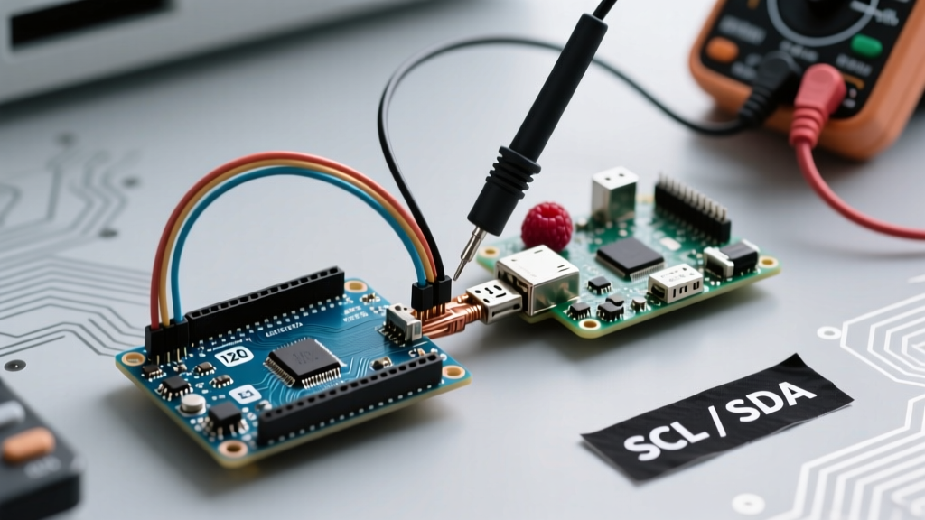
A common architecture in complex robotics is using the Raspberry Pi as the high-level I2C Master (running ROS or Python logic) and an Arduino Uno/Mega as the I2C Slave (handling PWM and ADC). Because the Arduino uses 5V logic and the Pi uses 3.3V, level shifting is mandatory.
The BSS138 MOSFET Solution
While resistor dividers work for unidirectional SPI, I2C is bi-directional. You must use a MOSFET-based level shifter like the BSS138 or a dedicated IC like the PCA9306 / Adafruit 4-Channel Bi-Directional Logic Level Converter. The BSS138 circuit isolates the high and low voltage sides, allowing the Pi's 1.8kΩ pull-ups to safely communicate with the Arduino's Wire.h library without frying the BCM chip.
Deep-Dive Troubleshooting FAQ
FAQ 1: Why do my I2C transfers randomly fail or corrupt on the Pi 4?
This is a well-documented silicon bug in the BCM2711 (Pi 4) and BCM2835 (Pi 3) I2C peripherals related to clock stretching. If an I2C slave (like an Arduino or a complex sensor) holds the SCL line low to stretch the clock during the ACK/NACK phase, the Pi's hardware controller can drop bits or corrupt the bus state.
The Fix: Bypass the hardware I2C controller and use software bit-banging via the i2c-gpio device tree overlay. Add this to your /boot/config.txt:
dtoverlay=i2c-gpio,i2c_gpio_sda=23,i2c_gpio_scl=24This creates a new, fully compliant software I2C bus (usually /dev/i2c-3) that handles clock stretching perfectly. Learn more about Pi configuration in the official Raspberry Pi documentation.
FAQ 2: Can I use GPIO 0 and 1 for my I2C sensors?
Technically yes, but it is highly discouraged. GPIO 0 and 1 map to i2c-0, which is reserved for HAT identification (the ID EEPROM). Polling devices on I2C0 can interfere with the Pi's boot sequence and HAT auto-configuration. Always use GPIO 2 and 3 (i2c-1).
FAQ 3: My Arduino I2C Slave freezes when the Pi reboots. Why?
When the Raspberry Pi reboots, the GPIO pins briefly float or toggle as the bootloader initializes. If the SDA line drops low while SCL remains high, the Arduino's I2C hardware peripheral can enter a 'bus lockup' state, thinking a transaction was interrupted.
The Fix: Implement a watchdog timer on the Arduino, or send a manual bus-clearing sequence (9 clock pulses on SCL) from the Pi immediately upon boot via a startup script before initializing your Python smbus2 or adafruit_blinka routines.
FAQ 4: What is the maximum bus capacitance and cable length?
The I2C specification limits bus capacitance to 400pF. With the Pi's 1.8kΩ pull-ups, this generally restricts cable length to about 30cm (12 inches) in noisy environments. For longer runs between a Pi and an Arduino, use twisted-pair CAT5 cable (pairing SDA with GND, and SCL with GND) or switch to differential I2C bus extenders like the PCA9615.
Summary Checklist for Flawless I2C Integration
- Verify 3.3V vs 5V logic levels and deploy MOSFET shifters if bridging to an Arduino.
- Confirm
i2cdetect -y 1shows your device at the correct hex address. - Check for 'UU' locks if a kernel driver has claimed your sensor.
- Apply the
i2c-gpiooverlay if your slave device utilizes clock stretching. - Keep trace/cable lengths under 30cm to respect the 400pF capacitance limit.
For a deeper understanding of the protocol's electrical characteristics, review the SparkFun I2C Tutorial. Mastering these hardware and OS-level quirks will save you hours of debugging and protect your equipment from catastrophic electrical failure.