
The Anatomy of Interrupt Multi-Counting
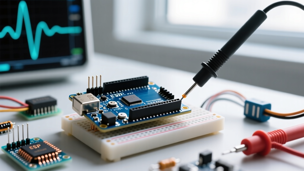
When diagnosing erratic behavior in microcontroller projects, few issues are as pervasive as the phantom trigger. If you are trying to figure out how to eliminate multi count on interrupt signal on Arduino or modern ARM-based boards like the RP2040, you are likely dealing with contact bounce or electromagnetic interference (EMI). Mechanical switches, such as the ubiquitous Omron B3F tactile series or Cherry MX keyswitches, do not make a clean electrical connection. Instead, the metal contacts physically collide, rebound, and settle over a period of 1 to 20 milliseconds. During this settling phase, an oscilloscope will reveal a rapid series of voltage spikes. If this signal is routed to a hardware interrupt pin using attachInterrupt(), the MCU will dutifully register dozens of triggers for a single physical button press.
According to the Arduino attachInterrupt() documentation, hardware interrupts pause the main program execution immediately. When switch bounce occurs, the ISR (Interrupt Service Routine) fires repeatedly in a fraction of a millisecond, corrupting state variables, freezing I2C buses, or causing severe timing drift in your main loop.
Hardware Diagnosis: Fixing Bounce at the Circuit Level
The most robust way to eliminate multi-counting is to prevent the erratic voltage spikes from ever reaching the microcontroller's GPIO pin. Hardware debouncing offloads the timing requirements from your CPU, ensuring the ISR only sees a clean, single digital edge.
The RC Low-Pass Filter Method
A simple resistor-capacitor (RC) network acts as a low-pass filter, smoothing out the high-frequency ringing of switch bounce. To implement this, place a 10kΩ pull-up resistor from the interrupt pin to VCC (5V or 3.3V). Connect your mechanical switch between the pin and GND. Next, insert a 1kΩ series resistor between the switch node and the MCU pin, and place a 100nF ceramic capacitor from the MCU pin to GND.
The time constant (τ) of this RC circuit is calculated as τ = R × C. With a 1kΩ resistor and a 100nF capacitor, τ = 0.1 milliseconds. It takes approximately 3τ to 5τ for the capacitor to charge or discharge past the MCU's logic threshold, yielding a hardware debounce window of 0.3ms to 0.5ms. If you are using a heavy-duty mechanical relay that bounces for 10ms, increase the capacitor to 1μF or the series resistor to 10kΩ to widen the filtering window.
Schmitt Trigger Buffering (74HC14)
While RC filters are cheap, they introduce a slow voltage slew rate. Microcontroller GPIO pins can sometimes exhibit metastability or increased current draw when held in the undefined voltage region between logic LOW and HIGH. To fix this, route the RC-filtered signal through a hex inverter with Schmitt trigger inputs, such as the TI SN74HC14. The Schmitt trigger utilizes hysteresis—meaning it has separate, distinct voltage thresholds for rising and falling edges—to snap the slow-moving RC curve into a razor-sharp digital square wave.
| Debounce Strategy | Latency Impact | Component Cost | CPU Overhead | Best Use Case |
|---|---|---|---|---|
| RC Low-Pass Filter | Low (1-10ms) | ~$0.02 | Zero | Simple pushbuttons, limit switches |
| Schmitt Trigger (74HC14) | Negligible (ns) | ~$0.15 | Zero | Noisy environments, long wire runs |
| Software Time-Window | Medium (5-50ms) | $0.00 | Minimal | Prototyping, cost-sensitive PCBs |
| Optocoupler (PC817) | Medium (3-5μs) | ~$0.10 | Zero | High-voltage isolation, industrial |
Software Diagnosis: ISR-Safe Debounce Algorithms
If your PCB is already manufactured or you are strictly prototyping on a breadboard, you must handle the multi-count issue in firmware. The golden rule of ISR design is to never use delay() inside an interrupt. Instead, utilize the micros() function to create a time-based rejection window. As detailed in Jack Ganssle's authoritative Guide to Debouncing, tracking the timestamp of the last valid edge allows you to ignore subsequent bounces.
volatile unsigned long last_isr_micros = 0;
volatile int trigger_count = 0;

void handleInterrupt() {
  unsigned long current_micros = micros();
  // 5000 microseconds = 5ms debounce window
  if (current_micros - last_isr_micros > 5000) {
    trigger_count++;
    last_isr_micros = current_micros;
  }
}

void setup() {
  pinMode(2, INPUT_PULLUP);
  attachInterrupt(digitalPinToInterrupt(2), handleInterrupt, FALLING);
}
Expert Compiler Note: Notice thevolatilekeyword applied tolast_isr_microsandtrigger_count. This instructs the GCC compiler (used for AVR and ARM cores) not to cache these variables in CPU registers, ensuring the main loop always reads the most recent value updated by the ISR.
Multicore MCU Considerations (ESP32 & RP2040)
In 2026, many makers have migrated from the single-core ATmega328P to dual-core architectures like the ESP32-S3 or Raspberry Pi RP2040. On these platforms, software debouncing requires additional synchronization. If your ISR runs on Core 1 while your main loop reads the counter on Core 0, you must implement a spinlock or mutex to prevent race conditions. On the ESP32, utilize portMUX_TYPE and portENTER_CRITICAL_ISR() to safely update shared volatile variables during the debounce timing check.
Advanced Edge Cases: EMI, Ground Bounce, and Encoders
Sometimes, what appears to be switch bounce is actually environmental noise. If you have implemented both RC filtering and software debouncing but are still seeing multi-counts, you must diagnose the physical wiring.
Electromagnetic Interference (EMI)
If your interrupt signal wire runs parallel to a DC motor, a solenoid, or an AC mains cable, the wire acts as an antenna. Inductive kickback from motors generates massive voltage transients that can capacitively couple into your GPIO trace, triggering the interrupt. The Fix: Use twisted-pair wiring for your switch signals, route them away from high-current paths, and add a 100nF bypass capacitor directly at the MCU pin. For extreme environments, isolate the signal entirely using a PC817 optocoupler.
Ground Bounce
When a high-current load (like an LED matrix or motor driver) switches on, it pulls a sudden surge of current through the ground plane. Due to the trace resistance and inductance of the PCB copper, the local ground reference for the MCU momentarily spikes upward. This 'ground bounce' can cause the voltage differential on the interrupt pin to cross the logic-low threshold, registering as a false trigger. Ensure your star-grounding topology separates high-current return paths from sensitive logic grounds.
Rotary Encoder Quadrature Errors
Rotary encoders generate two square waves (Phase A and Phase B) 90 degrees out of phase. If you are attaching an interrupt to Phase A to count pulses, mechanical bounce or EMI can cause the MCU to misread the state of Phase B, resulting in the counter oscillating wildly (counting up and down rapidly). To fix this, read the state of Phase B inside the Phase A ISR to determine direction, and apply a strict state-machine debounce algorithm rather than a simple time-delay rejection.
Diagnostic Summary Checklist
- Verify the Source: Hook an oscilloscope to the pin. Is the ringing high-frequency (contact bounce) or low-frequency/sparse (EMI)?
- Check Pull-ups: Never leave an interrupt pin floating. Always use
INPUT_PULLUPor an external 4.7kΩ to 10kΩ resistor. - Validate the Edge: Ensure you are triggering on
FALLINGorRISING, notCHANGE, unless strictly required by your protocol.CHANGEdoubles the interrupt load and exacerbates bounce issues. - Measure Latency: If your application requires sub-millisecond reaction times, abandon software debouncing and invest in hardware Schmitt triggers.