
The Hidden Pitfalls of Building an Arduino Clock with Alarm
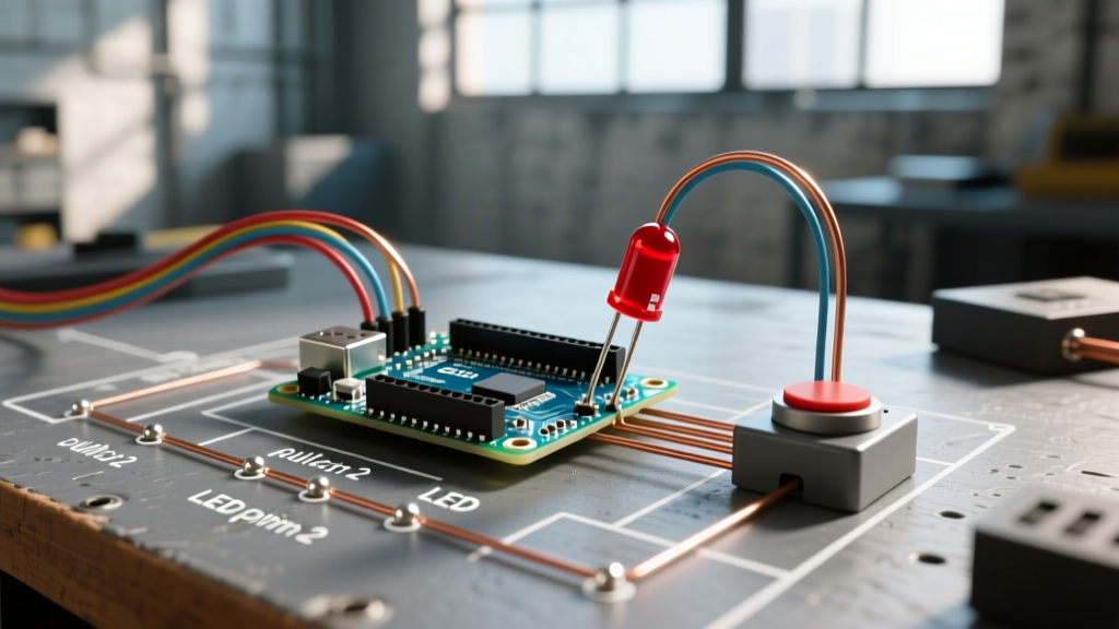
Building an arduino clock with alarm is a classic rite of passage for makers. On the surface, the architecture seems trivial: wire a Real-Time Clock (RTC) module to the I2C bus, attach a display, and trigger a buzzer when the time matches a target variable. However, when you transition from a breadboard prototype to a standalone bedside device, a wave of obscure edge cases often emerges. The display flickers when the buzzer sounds, the clock loses five minutes overnight, or the alarm simply refuses to trigger from deep sleep.
These failures rarely stem from flawed logic in your main loop; instead, they are rooted in hardware-level conflicts, I2C bus capacitance, and AVR interrupt misconfigurations. In this diagnostic guide, we dissect the four most common failure modes in Arduino alarm clock projects and provide exact, component-level solutions to ensure your device operates flawlessly in 2026 and beyond.
1. The 'Lost Time' Error: RTC Drift and the ZS-042 Battery Flaw
If your alarm triggers at the wrong time after a few days of operation, your RTC module is likely drifting or resetting. While the older DS1307 module is notorious for drifting up to 5 minutes per month due to temperature sensitivity, the DS3231SN utilizes an integrated Temperature-Compensated Crystal Oscillator (TCXO) to maintain accuracy within ±2ppm. According to the Analog Devices DS3231 datasheet, this translates to roughly 1 minute of drift per year. If your DS3231 is drifting more than this, you are likely facing a power delivery issue on the VBAT pin.
The ZS-042 Charging Circuit Hazard
Most hobbyists purchase the ubiquitous blue ZS-042 DS3231 breakout board. This module includes a charging circuit designed for LIR2032 rechargeable lithium cells. However, most makers use standard, non-rechargeable CR2032 cells. When main power (VCC) is connected, the ZS-042 attempts to charge the CR2032, causing the battery to overheat, leak, or fail prematurely. Worse, when main power is removed, the charging diode creates a voltage drop that starves the VBAT pin, causing the RTC to reset and lose time entirely.
Expert Fix: If you are using a non-rechargeable CR2032 on a ZS-042 module, you must physically remove the surface-mount diode (labeled D1) or the 200-ohm resistor near the battery holder. This disables the charging circuit, ensuring a clean 3.0V reaches the VBAT pin during power outages and preventing I2C lockups caused by brownout conditions.
I2C Bus Lockups and Pull-Up Resistor Sizing
Long wires between the ATmega328P and the RTC increase bus capacitance, leading to corrupted I2C read/write operations. The Arduino's internal pull-ups (roughly 20kΩ to 50kΩ) are far too weak for reliable high-speed I2C communication. Always add external 4.7kΩ pull-up resistors to both SDA and SCL lines. If your wiring exceeds 30cm, drop the pull-up resistors to 2.2kΩ to sharpen the signal rise times.
| RTC Module | Typical Drift | Common Failure Mode | Diagnostic Solution |
|---|---|---|---|
| DS1307 | ±5 mins/month | Temperature drift, I2C noise | Upgrade to DS3231; add 4.7kΩ pull-ups |
| DS3231 (ZS-042) | ±1 min/year | VBAT starvation, battery leakage | Remove D1 diode; use CR2032 |
| DS3231 (Adafruit) | ±1 min/year | None (Properly designed) | Ensure CR1220 is seated properly |
2. The 'Silent Alarm' Error: Deep Sleep and Interrupt Misconfigurations
To make a battery-operated or energy-efficient Arduino clock with alarm, you must put the microcontroller into deep sleep (Power-down mode) and rely on the RTC to wake it via an interrupt. A frequent error is the alarm firing once, but never again. This is almost always caused by failing to clear the RTC's internal alarm flag.
The Open-Drain SQW Pin and the A1F Flag
The DS3231 features an SQW/INT pin that pulls LOW when Alarm 1 or Alarm 2 matches the time registers. Because this pin is open-drain, it requires a pull-up resistor (usually 10kΩ to VCC) to register a HIGH state when inactive. More importantly, when the alarm triggers, the DS3231 sets the Alarm 1 Flag (A1F) in register 0x0F to logic 1. The SQW pin will remain LOW until your Arduino wakes up, reads the I2C bus, and manually writes a 0 to the A1F bit. If your ISR (Interrupt Service Routine) simply wakes the CPU without clearing this flag via I2C in the main loop, the next alarm will never trigger.
For a comprehensive breakdown of AVR sleep modes and interrupt vectors, Nick Gammon's authoritative guide on Arduino interrupts remains the gold standard for understanding how to safely interface I2C operations post-wake.
Wiring to the Correct Interrupt Vector
On the ATmega328P (Arduino Uno/Nano), only Pin 2 (INT0) and Pin 3 (INT1) support hardware interrupts capable of waking the chip from Power-down sleep. Pin Change Interrupts (PCINT) can also wake the chip, but they are notoriously difficult to debounce and configure for RTC square-wave outputs. Always wire the DS3231 SQW pin directly to Arduino Pin 2, and configure your code using attachInterrupt(digitalPinToInterrupt(2), wakeISR, FALLING).
3. The 'Flicker and Squeak' Error: Timer1 and Timer2 Conflicts
When your alarm triggers, you might notice the LED display (especially multiplexed 7-segment displays or MAX7219 matrices) flickering violently, or the piezo buzzer emitting a distorted, weak tone. This is a classic hardware timer collision.
The standard Arduino tone() function relies on Timer2 to generate the PWM square wave for the buzzer. However, many popular libraries also hijack Timer2. For instance, if your alarm clock includes an IR remote for setting the time, the IRremote library defaults to Timer2. Similarly, software-based display multiplexing often relies on TimerOne or Timer2 interrupts to refresh the digits.
Resolving the Timer Collision Matrix
- Scenario A (IR Remote + Buzzer): If using
IRremote, modify the library'sprivate.hfile to force it to use Timer1 or Timer3 (if using an ATmega2560), leaving Timer2 free for thetone()function. - Scenario B (Hardware PWM Buzzer): Bypass the
tone()function entirely. Wire your buzzer to Pin 9 or Pin 10, which are controlled by Timer1. UseanalogWrite()combined with a 555 timer IC or a dedicated audio amplifier chip like the PAM8403 to generate a clean, non-blocking alarm tone without disrupting your display refresh interrupts. - Scenario C (SPI Displays): If using a MAX7219 display, ensure you are using hardware SPI (Pins 11, 12, 13) rather than software bit-banging, which is easily interrupted by the buzzer's timer ISR, causing display corruption.
4. Power Supply Brownouts During Alarm Trigger
A subtle but devastating error occurs when the alarm actually sounds, but the Arduino immediately resets, silencing the alarm and rebooting the clock. This is a VCC brownout caused by sudden current spikes.
A standard 5V active piezo buzzer draws between 30mA and 50mA. If your alarm clock design includes a 5V relay module to switch on a bedside lamp, the relay coil can draw an additional 70mA to 90mA. When both trigger simultaneously, the sudden 140mA current spike causes a voltage drop across the USB cable resistance or the onboard AMS1117 linear regulator. If the ATmega328P's VCC drops below 2.7V (or 4.3V if the Brown-Out Detection fuse is set to 4.3V), the microcontroller triggers a hardware reset.
Capacitor Sizing and Transistor Isolation
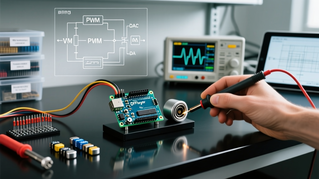
To diagnose this, connect an oscilloscope to the 5V rail and trigger the alarm. If you see the voltage dip below 4.5V, you need bulk capacitance. Solder a 470µF electrolytic capacitor directly across the VCC and GND rails near the microcontroller to act as a local energy reservoir. Furthermore, never drive a relay coil directly from the Arduino's 5V pin; use a logic-level MOSFET (like the IRLZ44N) or an optocoupler to isolate the relay's inductive kickback and current draw from the MCU's sensitive power rail. The SparkFun RTC Hookup Guide also emphasizes maintaining clean power rails to prevent I2C bus corruption during high-current switching events.
Diagnostic Summary Checklist
Before deploying your Arduino clock with alarm to its final enclosure, run through this hardware-level diagnostic checklist:
- Battery Circuit: Verify the ZS-042 charging diode is removed if using a CR2032 cell.
- I2C Integrity: Confirm 4.7kΩ pull-up resistors are present on SDA and SCL.
- Interrupt Wiring: Ensure the SQW pin is routed to Pin 2 (INT0) with a 10kΩ pull-up.
- Flag Clearing: Verify your post-wake I2C routine explicitly clears the A1F register bit.
- Timer Mapping: Check that
tone(),IRremote, and display libraries are not sharing Timer2. - Power Reservoir: Install a 470µF capacitor on the 5V rail to prevent brownout resets during alarm activation.
By addressing these specific electrical and architectural bottlenecks, you transform a fragile breadboard experiment into a robust, reliable timekeeping instrument capable of running for years without intervention.