
The Tethered Bottleneck in MCU Prototyping
For years, the standard Arduino workflow has relied on a fundamental crutch: the PC tether. Whether you are debugging via the Serial Monitor, dumping CSV data to a local hard drive, or relying on a PC to act as a USB host for peripheral inputs, your microcontroller remains leashed to a desktop. When deploying standalone data loggers or interactive kiosks, this tether forces engineers into inefficient workarounds, like soldering complex matrix keypads or wrestling with finicky SPI-based microSD card modules.
Enter the Arduino USB Host Shield. By integrating a dedicated USB host controller onto an Arduino-compatible footprint, this shield fundamentally shifts your development workflow from PC-dependent to truly standalone. In this guide, we explore how leveraging USB Host capabilities optimizes data logging, accelerates HID (Human Interface Device) integration, and eliminates common field-deployment friction points.
Hardware Anatomy and 2026 Market Realities
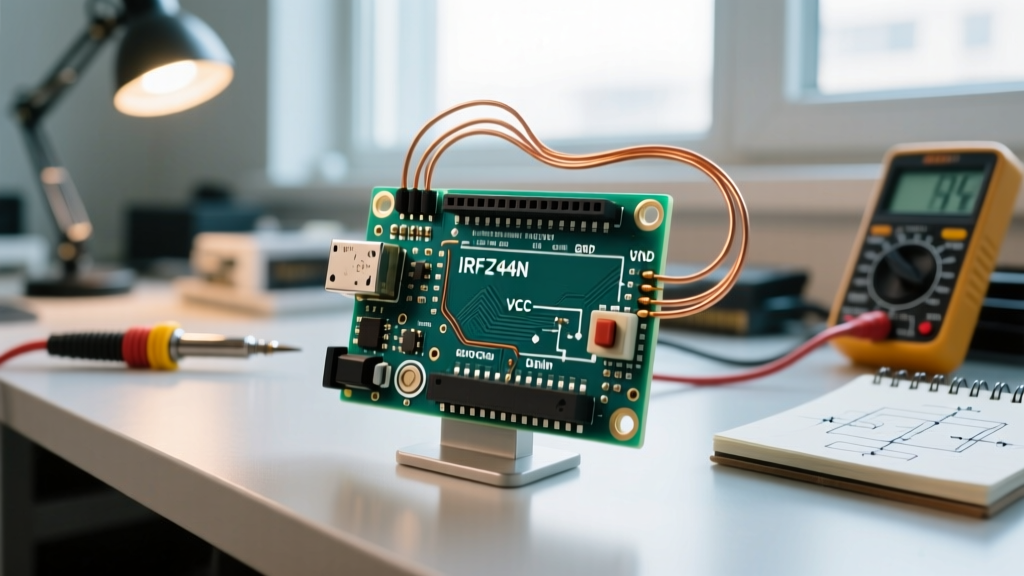
At the heart of almost every Arduino USB Host Shield is the MAX3421E USB host/peripheral controller. This chip handles the complex, low-level USB 2.0 Full-Speed (12 Mbps) protocol stack in hardware, communicating with your microcontroller via a standard SPI bus. This offloading is critical; an ATmega328P lacks the clock speed and RAM to bit-bang or natively process USB enumeration and packet framing.
Pricing and Sourcing
As of 2026, the market is split between original designs and mass-produced clones:
- Genuine Circuits@Home Shields: Priced around $45–$55. These feature high-quality level-shifting, robust decoupling capacitors, and guaranteed compatibility with 3.3V and 5V logic boards.
- Generic Clones (SainSmart, Deegoo, AliExpress): Priced between $12 and $18. While cost-effective for bulk deployments, clones often cut corners on logic-level translation and power regulation, requiring specific workflow adjustments (detailed below).
Workflow Shift: SD Cards vs. USB Mass Storage
The most significant workflow optimization the shield provides is in data logging. Traditionally, engineers use SPI microSD modules. While cheap, SD cards introduce severe field-work friction: they are easily lost, prone to FAT32 corruption if power is cut during a write cycle, and require a separate card reader to ingest data on a PC.
By utilizing the USB Host Shield 2.0 library maintained by Oleg Mazurov (felis), you can interface directly with standard USB thumb drives. The end-user simply plugs in a high-capacity USB drive, the Arduino writes the CSV data, and the user pulls the drive to plug directly into their laptop. No adapters, no lost cards.
Storage Medium Comparison Matrix
| Feature | SPI microSD Module | USB Host Shield (Mass Storage) | PC Serial Tether |
|---|---|---|---|
| Field Swappability | Poor (tiny, easily dropped) | Excellent (standard thumb drive) | None (requires laptop) |
| Max Practical Capacity | 32GB (FAT32 limits) | 128GB+ (exFAT/FAT32) | Limited by PC HDD |
| Corruption Risk | High (SPI bus noise) | Low (Hardware error correction) | Zero |
| Setup Complexity | Low (Hardware), High (FAT) | Medium (Library config) | Low |
Accelerating Input Workflows with USB HID
Building custom input interfaces is a massive time sink. If your project requires barcode scanning, RFID entry, or complex alphanumeric input, designing a custom PS/2 or I2C keypad matrix can add weeks to your development cycle.
The USB Host Shield allows you to bypass custom hardware design entirely. By using the HIDBoot.h module within the library, an Arduino can instantly read input from commercial, off-the-shelf USB barcode scanners or standard desktop keyboards.
Workflow Pro-Tip: In 2026, most commercial USB barcode scanners default to 'Keyboard Wedge' (HID) mode. You do not need to write custom USB descriptor parsers. The Arduino simply reads the scanner as a standard keyboard, capturing the scanned string and the 'Enter' keystroke in milliseconds.
Critical Edge Cases and Troubleshooting
To truly optimize your workflow, you must anticipate the hardware failure modes inherent to SPI-based USB hosting. Clone shields, in particular, are notorious for causing silent failures if not properly configured.
1. The Power Brownout Trap
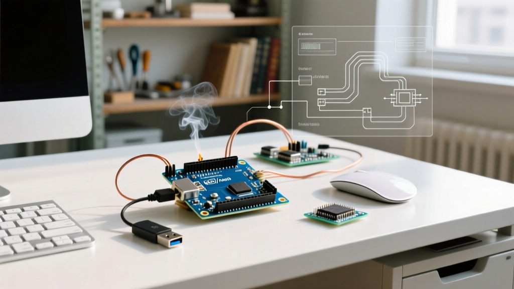
The USB specification allows a connected device to draw up to 500mA. When a USB thumb drive spins up its internal controller, or a barcode scanner activates its laser, current spikes can exceed 300mA. If you are powering your Arduino Uno via the standard USB-B port or a 9V barrel jack, the onboard linear voltage regulator will overheat and trigger thermal shutdown, causing the microcontroller to reset endlessly.
The Fix: For standalone deployments, bypass the onboard regulator. Supply a clean, regulated 5V directly to the Arduino's 5V pin using an external buck converter (like an LM2596 module) rated for at least 2A. This ensures the MAX3421E and the connected USB device receive stable power without thermal throttling.
2. Logic Level Mismatches
The MAX3421E chip operates natively at 3.3V. While its VBUS pin handles 5V USB power, the SPI data lines (MOSI, MISO, SCK, SS) are often strictly 3.3V tolerant. Connecting a 5V Arduino Uno directly to a cheap clone shield without level shifting can slowly degrade the MAX3421E silicon or cause intermittent SPI read errors.
The Fix: If using a 5V microcontroller with a clone shield, route the SPI lines through a bidirectional logic level converter (such as a BSS138 MOSFET-based shifter or a CD4050BE buffer). For a comprehensive guide on implementing these safely, refer to SparkFun's tutorial on logic level conversion. Alternatively, migrate your workflow to a 3.3V native board like the Arduino Due or an ESP32, ensuring you use the correct SPI pins for those specific architectures.
3. SPI Clock Speed Desynchronization
Some mass-produced clone shields suffer from poor PCB trace routing, leading to signal integrity issues at the default 8MHz or 12MHz SPI clock speeds. This manifests as the shield failing to initialize or USB drives failing to mount.
The Fix: You can software-throttle the SPI bus. In the UsbCore.h file of the library, locate the MAX3421E_SPI_SPEED definition and drop it to SPI_CLOCK_DIV4 or lower. This slight reduction in bus speed dramatically increases reliability on marginal hardware without noticeably impacting USB throughput, as the MAX3421E's internal USB processing is the actual bottleneck, not the SPI transfer rate.
Physical Design Considerations for 2026
One modern friction point is the physical port. The Arduino USB Host Shield features a legacy USB Type-A receptacle. With the industry standard having shifted firmly to USB-C for both mobile devices and modern thumb drives, your physical workflow must adapt. Always keep a high-quality, short USB-A to USB-C OTG adapter in your deployment kit. Avoid long, passive extension cables, as they introduce voltage drop that can trigger the aforementioned power brownouts.
Conclusion
Integrating an Arduino USB Host Shield transforms your microcontroller from a tethered development node into a robust, standalone appliance. By offloading data storage to high-capacity USB drives and leveraging commercial HID peripherals for input, you eliminate weeks of custom hardware design and field-maintenance headaches. While it requires careful attention to power delivery and SPI logic levels, the resulting workflow optimization makes it an indispensable tool for professional MCU deployments.
For deep-dive hardware schematics and pinout diagrams, engineers should consult the original Circuits@Home USB Host Shield Hardware Manual, which remains the definitive reference for MAX3421E integration.