
Building an Arduino CO2 monitor is a staple project for indoor air quality tracking, greenhouse automation, and HVAC optimization. However, makers frequently run into maddening issues: sensors stuck at a baseline of 400 PPM, I2C bus lockups, or wild fluctuations that render the data useless. Unlike simple temperature sensors, CO2 modules rely on complex NDIR (Non-Dispersive Infrared) or photoacoustic spectroscopy, requiring precise timing, logic-level matching, and strict calibration protocols.
This comprehensive troubleshooting guide dives deep into the most popular Arduino CO2 sensors—the UART-based Winsen MH-Z19B and the I2C-based Sensirion SCD30/SCD40. We will dissect hardware wiring traps, firmware communication errors, and calibration drift, providing exact fixes to get your air quality monitor back online.
NDIR UART Sensors: Fixing MH-Z19B Communication Drops
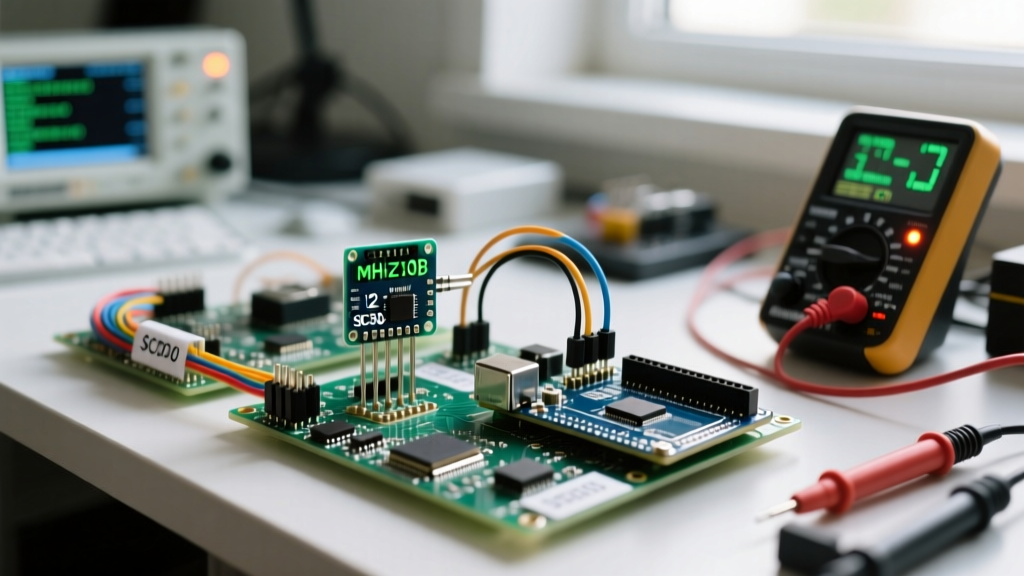
The Winsen MH-Z19B is the most ubiquitous budget NDIR CO2 sensor in the maker community. It communicates via UART (serial) at a default baud rate of 9600. When your Arduino Serial Monitor outputs gibberish, zeros, or fails to request data, the issue almost always stems from logic level mismatches or malformed command checksums.
The 5V to 3.3V Logic Level Trap
The MH-Z19B operates on 5V power and expects 5V UART logic on its RX pin. If you are using a 3.3V microcontroller like the ESP32, Arduino Due, or an Adafruit Feather, connecting the 3.3V TX pin directly to the sensor's RX pin will result in intermittent failures or complete unresponsiveness. Conversely, the sensor's TX pin outputs 5V, which can fry the GPIO pins of a 3.3V ESP32.
- The Fix (TX to Sensor RX): Use a bi-directional logic level converter (like the BSS138) or a simple voltage divider (1.5kΩ and 2.2kΩ resistors) to step up the 3.3V signal to ~4.8V.
- The Fix (Sensor TX to MCU RX): You must step down the 5V output from the sensor using a voltage divider to prevent permanent damage to your 3.3V microcontroller.
Checksum Calculation Failures
The MH-Z19B requires a 9-byte command array for every request. The 9th byte is a checksum. If your Arduino library is outdated or you are writing raw byte arrays, a miscalculated checksum will cause the sensor to silently ignore the request. The checksum formula is: 0xFF - (Byte1 + Byte2 + Byte3 + Byte4 + Byte5 + Byte6 + Byte7). Ensure your variables are cast to byte or uint8_t to prevent integer overflow during the addition phase before the final subtraction.
I2C Photoacoustic Sensors: Resolving SCD30 Bus Lockups
For high-accuracy applications, the Sensirion SCD30 and SCD40 are the gold standards. They use photoacoustic sensing and communicate via I2C (address 0x61). A common failure mode is the I2C bus "locking up," where the Arduino Wire library hangs indefinitely during a Wire.requestFrom() call.
Clock Stretching & Pull-Up Resistor Sizing
The SCD30 utilizes I2C clock stretching—a mechanism where the sensor holds the SCL (clock) line LOW while it processes data. Many default Arduino and ESP32 I2C implementations have strict timeout limits or fail to handle clock stretching correctly, leading to bus lockups.
- Reduce I2C Clock Speed: The SCD30 can struggle with the default 100kHz or 400kHz I2C speeds when combined with long wires. Add
Wire.setClock(50000);in yoursetup()loop to drop the bus speed to 50kHz, giving the sensor ample time to stretch the clock. - Verify Pull-Up Resistors: The SCD30 breakout boards usually include 10kΩ pull-up resistors. If you are wiring multiple I2C sensors on the same bus, the parallel resistance drops, potentially pulling the signal below the I2C logic threshold. Ensure the total pull-up resistance on the SDA and SCL lines remains between 2.2kΩ and 10kΩ.
- Respect the Measurement Interval: Do not poll the SCD30 continuously. Set the measurement interval to at least 2 seconds using the
setMeasurementInterval(2)command. Polling the data-ready register too frequently can overwhelm the sensor's internal state machine.
Calibration Drift: Manual vs. Automatic Background Calibration
A frequent complaint on maker forums is that an Arduino CO2 monitor slowly drifts over weeks, eventually reporting 350 PPM in a crowded room. This is caused by a misunderstanding of Automatic Background Calibration (ABC).
Expert Insight: ABC logic assumes that at least once every 7 to 14 days, the sensor will be exposed to fresh outdoor air (400 PPM). If your Arduino CO2 monitor is deployed in a sealed bedroom, a basement, or a greenhouse, ABC will falsely calibrate the lowest indoor reading as 400 PPM, destroying your absolute accuracy.
| Calibration Method | How It Works | Best Use Case | Risk Factor |
|---|---|---|---|
| ABC (Automatic) | Tracks the lowest reading over 14 days and sets it as 400 PPM. | Living rooms, offices with regular fresh air exchange. | High drift in sealed environments or greenhouses. |
| Manual Single-Point | Forces the sensor to map the current reading to 400 PPM via UART/I2C command. | Sealed rooms, bedrooms, grow tents. | Requires physically moving the sensor outdoors for 20+ minutes before triggering. |
| Two-Point (Factory) | Maps 0 PPM (Nitrogen) and 2000 PPM (Reference Gas). | Laboratory and industrial safety applications. | Requires expensive certified reference gas mixtures. |
The Fix: If deploying in a sealed environment, disable ABC via the sensor's specific disable command (e.g., 0xFF 0x01 0x79 0x00 0x00 0x00 0x00 0x00 0x86 for the MH-Z19B). Perform a manual calibration by placing the sensor outside in the shade, away from exhaust vents, for 30 minutes, and then send the manual calibration trigger command.
The eCO2 Illusion: CCS811 vs. True NDIR Sensors
Before tearing apart your hardware, verify the actual technology inside your sensor module. Modules like the CCS811, SGP30, and BME688 do not measure true CO2. They measure Volatile Organic Compounds (VOCs) and use an onboard algorithm to estimate "equivalent CO2" (eCO2).
If your Arduino CO2 monitor spikes to 2000 PPM when you peel an orange or use hand sanitizer, you are using a VOC-based eCO2 sensor. These sensors are highly susceptible to "burn-in" drift and require a 48-hour continuous power burn-in period before their algorithmic baselines stabilize. If you require true, actionable CO2 data for ventilation control, you must replace the module with an NDIR (MH-Z19) or Photoacoustic (SCD30) sensor.
Master Troubleshooting Checklist
When your sketch compiles but the data is missing or invalid, follow this sequential Arduino Wire and Serial debugging flow:
- Step 1: I2C Scanner. Run the standard Arduino I2C Scanner sketch. If the SCD30 does not show up at
0x61, check your solder joints and pull-up resistors. - Step 2: UART Loopback. For the MH-Z19B, disconnect the sensor. Connect your Arduino's TX directly to its RX. Send a character via the Serial Monitor; if it echoes back, your MCU's serial port is functional.
- Step 3: Logic Analyzer. If you have access to a $10 USB logic analyzer, capture the SDA/SCL or TX/RX lines. Look for NACKs (SDA staying HIGH on the 9th clock pulse) which indicate the sensor is rejecting the I2C address or command.
- Step 4: Power Supply Sag. NDIR sensors draw spikes of current (up to 150mA) when the internal IR LED fires. If powering from the Arduino's 5V pin, the voltage regulator may sag, resetting the sensor. Power the sensor directly from a dedicated 5V USB buck converter.
By isolating the protocol layer, verifying logic voltages, and applying the correct calibration strategy for your specific physical environment, you can transform an erratic Arduino CO2 monitor into a highly reliable, lab-grade air quality instrument.