
The Anatomy of KY-023 and PS2 Joystick Modules
When integrating an analog joystick Arduino setup, most makers rely on the ubiquitous KY-023 or PS2 dual-axis breakout boards. Priced between $1.50 and $3.00 on the surplus market, these modules utilize two 10kΩ potentiometers (one for the X-axis, one for the Y-axis) and a momentary tactile switch for the Z-axis (select button). While they are excellent for prototyping, their carbon-track potentiometers are highly susceptible to mechanical wear, dust ingress, and electrical noise.
Troubleshooting these modules requires a systematic approach that bridges hardware diagnostics with software signal conditioning. In 2026, with the maker market flooded with ultra-cheap clones featuring poorly screened resistive elements, understanding the underlying failure modes is critical for building reliable human-machine interfaces (HMIs).
Diagnostic Troubleshooting Matrix
Before rewriting your sketch, use this matrix to isolate whether your issue is rooted in wiring, hardware degradation, or ADC (Analog-to-Digital Converter) misconfiguration.
| Symptom | Probable Cause | Hardware / Software Fix |
|---|---|---|
| Center value reads ~675 instead of ~512 | Module powered by 3.3V, but Arduino ADC reference is 5V | Wire VCC to 5V, or use analogReference(DEFAULT) matching VCC |
| Values fluctuate wildly at rest (±20 points) | ADC noise / High impedance carbon track | Add 100nF capacitor to ground; apply EMA software filter |
| SW (Select) button reads random 0/1023 | Floating pin state due to missing pull-up resistor | Change pinMode to INPUT_PULLUP |
| Axis maxes out early or feels 'scratchy' | Physical wear on the potentiometer carbon wiper | Clean with DeoxIT D5 or upgrade to an Alps Alpine hall-effect module |
Fix 1: Resolving Axis Drift and the '512' Center Point Myth
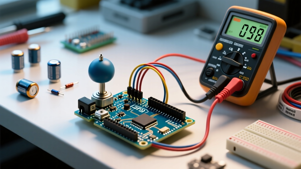
A frequent complaint on maker forums is that the joystick's resting position does not read exactly 512 (the theoretical midpoint of the Arduino's 10-bit, 0-1023 ADC range). This 'drift' is rarely a software bug; it is almost always a voltage reference mismatch.
The VCC vs. VREF Mismatch
The Arduino Uno R3 and Nano operate their ADCs using the board's 5V logic level as the default reference voltage (DEFAULT). If you wire the joystick's VCC pin to the Arduino's 3.3V pin (often done to accommodate 3.3V logic boards like the ESP32 or Arduino Nano 33 IoT), the maximum voltage the joystick can output is 3.3V.
When the 5V-referenced ADC reads that 3.3V maximum, it calculates: (3.3 / 5.0) * 1023 ≈ 675. Therefore, your center point shifts from 512 to roughly 337, and your maximum throw caps at 675.
Pro Tip: Always match your joystick VCC to your Arduino's analog reference voltage. If you must run the joystick at 3.3V on a 5V Arduino, call
analogReference(EXTERNAL)and wire the 3.3V pin to the AREF pin, or use themap()function to recalibrate the expected software bounds.
Fix 2: Eliminating ADC Jitter with Hardware and Software Filters
If your serial monitor shows the X and Y axes jumping between 505 and 518 while the joystick is completely untouched, you are experiencing ADC jitter. The Arduino's successive approximation ADC is highly sensitive to high-impedance sources and electromagnetic interference (EMI).
Hardware Fix: The 100nF Bypass Capacitor
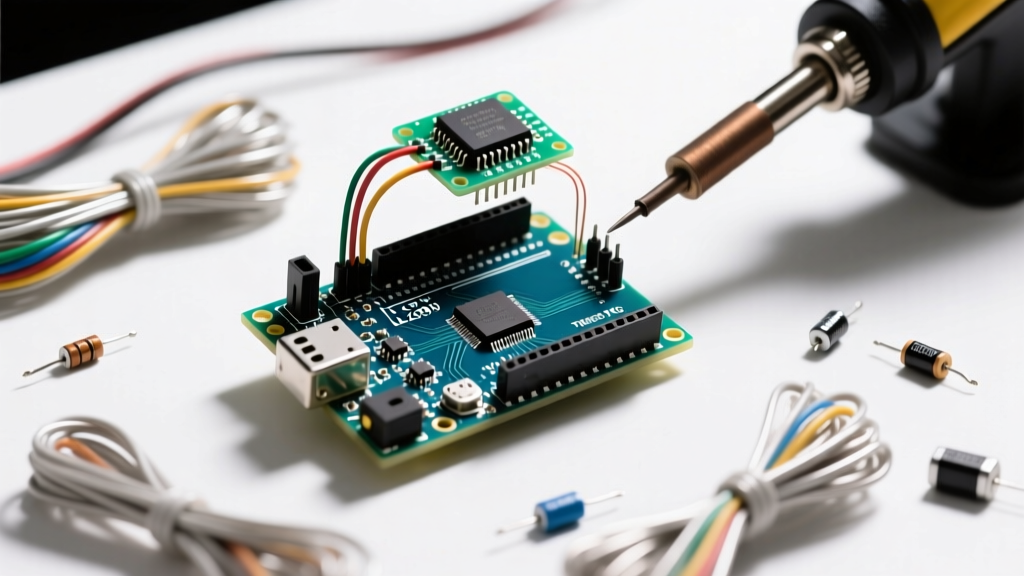
The most effective way to stabilize an analog joystick Arduino circuit is to add a 100nF (0.1µF) ceramic capacitor between the VRx signal pin and GND, and a second one between VRy and GND. This creates a low-pass RC filter that physically shorts high-frequency noise to ground before it reaches the microcontroller's ADC pin. According to Arduino's official analogRead documentation, keeping the source impedance below 10kΩ is vital for accurate sampling; the capacitor effectively lowers the impedance for high-frequency transients.
Software Fix: Exponential Moving Average (EMA)
If you cannot modify the hardware, implement an Exponential Moving Average filter in your C++ sketch. Unlike a simple rolling average that requires storing arrays of past data, an EMA uses a fraction of the new reading and a fraction of the old reading, consuming minimal SRAM.
// EMA Filter for Joystick Jitter
float alpha = 0.15; // Smoothing factor (0.0 to 1.0). Lower = smoother but more lag.
float filteredX = 512.0; // Initialize at center

void setup() {
  Serial.begin(115200);
}

void loop() {
  int rawX = analogRead(A0);
  filteredX = (alpha * rawX) + ((1.0 - alpha) * filteredX);

  Serial.println((int)filteredX);
  delay(10);
}
Fix 3: The SW (Select) Pin Floating State Trap
The KY-023 module's select button (labeled 'SW') is wired directly to the wiper of a momentary switch. When the button is not pressed, the pin is physically disconnected from both VCC and GND. In microcontroller terminology, this is a floating pin.
If you configure this pin as a standard INPUT, the Arduino's high-impedance input will act like an antenna, picking up ambient EMI and returning random 0s and 1023s. To fix this, you must engage the microcontroller's internal 20kΩ pull-up resistor. As detailed in the Arduino INPUT_PULLUP reference, this safely biases the pin to HIGH (1) when the switch is open, and pulls it to LOW (0) when the switch connects the pin to GND.
const int swPin = 2;

void setup() {
  pinMode(swPin, INPUT_PULLUP); // Engages internal 20k pull-up resistor
  Serial.begin(9600);
}

void loop() {
  // Reads LOW (0) when pressed, HIGH (1) when released
  int buttonState = digitalRead(swPin);
  if (buttonState == LOW) {
    Serial.println("Joystick Pressed!");
  }
}
Fix 4: Mechanical Wear and Carbon Track Degradation
If your joystick outputs erratic spikes (e.g., jumping from 300 directly to 800) when moved slowly, the physical carbon track inside the potentiometer is degraded. This is incredibly common on sub-$2 generic modules where the wiper contact pressure is poorly calibrated, leading to micro-arcing and carbon dust buildup.
Restoring vs. Upgrading
For a quick restoration, carefully pry off the metal housing of the potentiometer and spray the carbon track with a specialized contact cleaner like DeoxIT D5. Avoid standard WD-40, which leaves a conductive, dust-attracting residue that will permanently ruin the module.
However, for projects requiring high durability (such as RC transmitters or industrial control panels), abandon carbon-track potentiometers entirely. Upgrade to a Hall-effect based joystick, such as the Alps Alpine RKJXT1F42001 (approx. $4.50) or the Adafruit Analog Thumb Joystick (Product ID 2765, approx. $9.95). Hall-effect sensors use magnetic fields to determine position, meaning there is zero physical contact on the sensing element, completely eliminating carbon wear and guaranteeing a lifespan of over 1,000,000 cycles.
Summary Checklist for Makers
- Verify VCC: Ensure joystick VCC matches the Arduino's Analog Reference Voltage.
- Filter Noise: Solder 100nF capacitors on the X and Y signal lines.
- Use Pull-ups: Always declare the SW pin as
INPUT_PULLUP. - Implement Deadzones: Map the center 490-530 range to a flat '0' output in software to prevent drift in motor control applications.
- Upgrade Hardware: Switch to Hall-effect modules for mission-critical or high-use applications.
By combining proper electrical biasing with digital signal conditioning, you can transform a jittery, unreliable breakout board into a precision input device suitable for advanced robotics and IoT interfaces.