
The Anatomy of ESP32-CAM Failures
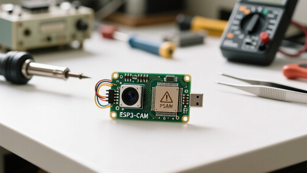
The AI-Thinker esp32 cam module has become a staple in the maker community for DIY security cameras, edge-AI object detection, and remote timelapse projects. However, its compact footprint and aggressive cost-cutting measures result in a notoriously steep learning curve. Unlike standard development boards, the ESP32-CAM lacks an integrated USB-to-UART bridge, features a marginal onboard voltage regulator, and routes high-speed camera signals through a delicate ribbon cable.
When you encounter endless serial monitor loops, silent failures, or immediate reboots, the issue rarely lies in your C++ sketch. Instead, it is almost always a collision between hardware power limitations, incorrect strapping pin states, or IDE misconfigurations. This guide dissects the most critical failure modes of the esp32 cam module and provides exact, field-tested solutions to get your vision projects online.
Critical Hardware Prerequisites: The Power Trap
The most frequent point of failure for beginners is misunderstanding the power delivery architecture of the AI-Thinker board. The module features an AMS1117-3.3 LDO (Low Dropout) voltage regulator. While the datasheet for the AMS1117 claims an 800mA output, the physical implementation on the ESP32-CAM—combined with the thermal mass of the PCB—means it cannot sustain high currents without severe voltage droop.
The 5V vs 3.3V Pin Misconception
When the ESP32 initializes the WiFi radio and simultaneously powers the OV2640 image sensor, current spikes can easily exceed 240mA. If you attempt to power the module by feeding 3.3V directly into the 3V3 pin from a standard FTDI programmer (which typically maxes out at 50mA to 100mA on its internal LDO), the voltage will collapse. The ESP32's internal brownout detector will instantly trigger a reset.
The Fix: Always supply power to the 5V pin on the ESP32-CAM when using an external FTDI adapter. The onboard AMS1117 will step this down to 3.3V much more reliably than a weak external 3.3V source. For production or standalone deployments, bypass the onboard LDO entirely by using a high-quality external buck converter (like an MP1584) set to exactly 3.3V, feeding directly into the 3V3 pin while removing the 0-ohm resistor linking the LDO output.
FTDI Programmer Wiring Matrix
Correct wiring is non-negotiable. A single crossed wire will result in failed uploads or damaged silicon. Ensure your FTDI adapter is set to 3.3V logic levels via its physical jumper before connecting.
| FTDI Programmer Pin | ESP32-CAM Pin | Function & Notes |
|---|---|---|
| GND | GND | Common ground reference. Essential for stable logic. |
| VCC (5V) | 5V | Primary power input. Do NOT use 3V3 pin here. |
| TXD | U0R (RX) | FTDI Transmit to ESP32 Receive. |
| RXD | U0T (TX) | FTDI Receive to ESP32 Transmit. |
| N/A | GPIO0 | Must be jumpered to GND ONLY during flash upload. |
Decoding the 'Camera Init Failed' Error
Seeing Camera init failed with error 0x20001 or 0x105 in your serial output is a rite of passage. These errors indicate that the ESP32's I2C/SCCB bus cannot communicate with the camera sensor's internal registers. According to the Espressif Camera Driver API Reference, these codes map to specific hardware and configuration faults.
Error 0x20001: Physical Connection & Sensor Seating
This error means the microcontroller is sending clock signals but receiving no acknowledgment from the OV2640 sensor.
- Ribbon Cable Fatigue: The 24-pin FPC (Flexible Printed Circuit) connector is fragile. Ensure the black locking flap is gently lifted before inserting the cable. The blue stiffener on the cable must face the correct direction (usually towards the PCB surface, but verify against your specific board revision).
- Oxidation: If the module sat in a humid environment, the gold fingers on the ribbon cable may have oxidized. Carefully clean them with isopropyl alcohol and a cotton swab.
Error 0x105: PSRAM Configuration Mismatches
The ESP32 requires external PSRAM to buffer image frames, especially at resolutions above QVGA. If the Arduino IDE is not configured to utilize the 8MB PSRAM chip located on the bottom of the AI-Thinker board, the camera driver will fail to allocate memory, throwing a 0x105 or 0x103 error.
The Fix: In the Arduino IDE, navigate to Tools > Board and ensure you have selected AI Thinker ESP32-CAM. Selecting the generic 'ESP32 Dev Module' will disable the specific PSRAM memory mapping required for the camera. Furthermore, verify that Tools > PSRAM is explicitly set to Enabled. For newer boards utilizing OPI (Octal SPI) PSRAM instead of QSPI, you may need to update your ESP32 board manager package to version 2.0.14 or higher to access the correct OPI initialization arrays.
Conquering the Brownout Detector Reset Loop
If your serial monitor repeatedly prints the following message, you are experiencing a brownout:
ets Jun 8 2016 00:22:57

rst:0xc (SW_CPU_RESET),boot:0x13 (SPI_FAST_FLASH_BOOT)

Brownout detector was triggered
The ESP32 features an internal hardware monitor tied to the RTC_CNTL_BROWN_OUT_REG. If the VDD33 rail drops below approximately 2.43V for even a microsecond during a WiFi transmission spike, the system intentionally triggers a software reset to prevent flash memory corruption.
Capacitor and Regulator Solutions
To stabilize the power rail, you must provide a local energy reservoir. Soldering a 100µF to 470µF electrolytic capacitor directly across the 5V and GND pins on the header will absorb transient current spikes. For a more robust fix, especially if you are also powering servos or LEDs from the same rail, use a dedicated 3A buck converter module. As detailed in the Random Nerd Tutorials ESP32-CAM Troubleshooting Guide, disabling the WiFi radio when not actively transmitting, or putting the ESP32 into deep sleep between captures, can also drastically reduce the frequency of brownout events.
Flash & Upload Failures: GPIO0 and Boot Modes
A completely different class of errors occurs before your code even runs: Failed to connect to ESP32: Timed out waiting for packet header. This means the Arduino IDE cannot place the module into UART download mode.
The ESP32 relies on 'strapping pins' to determine its boot behavior upon reset. GPIO0 is the critical pin for flashing.
- Connect GPIO0 to GND via a jumper wire.
- Press and release the physical RESET button on the back of the ESP32-CAM module while GPIO0 remains grounded.
- Initiate the upload from the Arduino IDE.
- Once the IDE reports 'Hard resetting via RTS pin...', remove the GPIO0 to GND jumper and press the RESET button one final time to boot into your newly flashed application.
Thermal, RF, and Sensor Variations
Finally, hardware selection impacts software stability. The standard AI-Thinker board ships with an OV2640 sensor. If you upgrade to an OV5640 (5-megapixel) module, you must use a completely different initialization array in your code. The OV5640 draws significantly more current and requires explicit I2C clock speed adjustments in the esp_camera.h configuration struct to prevent bus timeouts.
Regarding RF performance, the ESP32-CAM features both a PCB trace antenna and an IPEX U.FL connector for an external antenna. By default, the PCB antenna is active. If you are placing the module inside a metal enclosure or experiencing severe WiFi packet loss, you must desolder the 0-ohm resistor near the IPEX connector and move it to the adjacent pad to route the RF signal to the external antenna port. For exact schematic locations, refer to the AI-Thinker ESP32-CAM Pinout and Schematic documentation.
Summary Checklist for Stable Operation
- Power via the 5V pin using a minimum 1A capable supply.
- Select 'AI Thinker ESP32-CAM' and enable PSRAM in the IDE.
- Verify ribbon cable seating and clean contacts if I2C errors persist.
- Add bulk capacitance (100µF+) to suppress brownout resets.
- Manually strap GPIO0 to GND and cycle reset for stubborn upload failures.
By systematically addressing power delivery, strapping pin logic, and IDE memory mapping, you can transform the esp32 cam module from a frustrating puzzle into a highly reliable platform for embedded computer vision.