
The Architecture Shift: Why the ESP32-C6 Pinout is Different
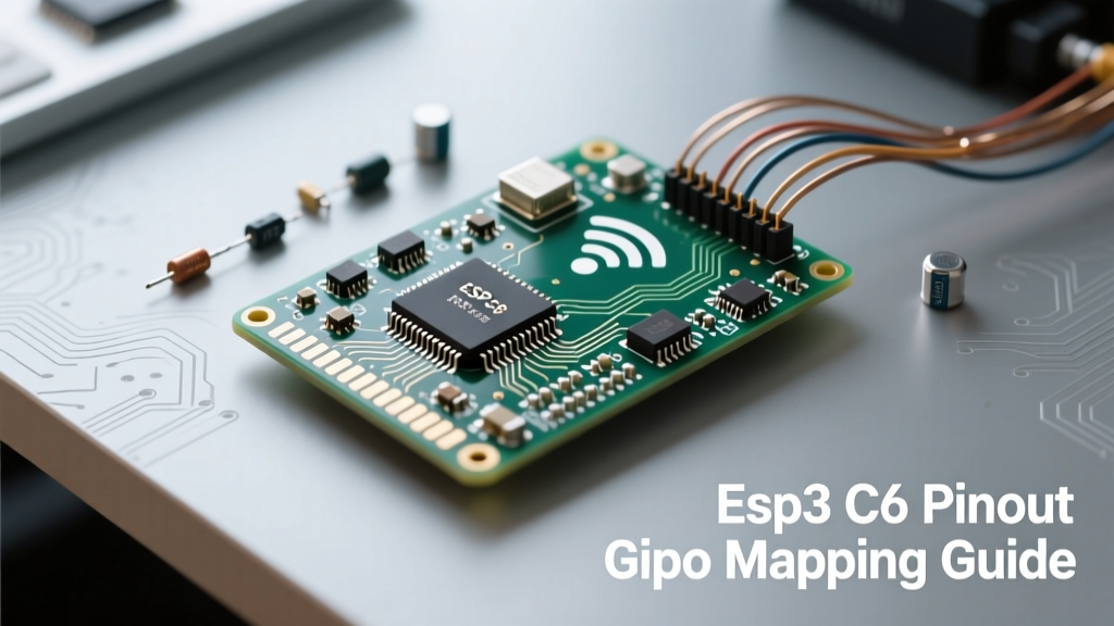
The transition from the classic Xtensa-based ESP32 to the RISC-V architecture in the ESP32-C6 represents a massive leap for IoT hardware designers. When analyzing the ESP32-C6 pinout, you are not just looking at a reshuffled array of I/O; you are looking at a silicon layout optimized for Wi-Fi 6 (802.11ax), Bluetooth 5 (LE), Zigbee, and Thread (Matter) coexistence. Unlike the ESP32-S3, which targets high-performance dual-core applications with Octal SPI, the ESP32-C6 is engineered for low-power, high-efficiency mesh networking and smart home endpoints.
For electrical engineers and advanced makers, understanding this pinout requires moving beyond simple breadboard wiring. The ESP32-C6 features a highly flexible GPIO Matrix, but it is bounded by strict hardware strapping requirements, internal flash routing, and RF keepout zones. This guide deconstructs the ESP32-C6-WROOM-1 module pinout, providing the actionable frameworks needed to design robust custom PCBs without falling victim to common boot-loop traps or signal integrity failures.
Core GPIO Matrix: Usable Pins vs. Flash/SPI Reserved
The bare ESP32-C6 silicon boasts 30 General Purpose Input/Output (GPIO) pins. However, if you are designing with the ubiquitous ESP32-C6-WROOM-1 module, several of these pins are permanently consumed by the internal SPI Flash and PSRAM architecture. Specifically, GPIOs 24 through 29 are dedicated to the internal SPI flash interface and are physically inaccessible on the module's castellated pads.
The 30-GPIO Reality Check
Out of the 30 theoretical pins, makers typically have access to 22 fully usable GPIOs on the standard WROOM-1 variant. Every usable pin on the ESP32-C6 supports digital functions, interrupt triggering, and the GPIO Matrix, which allows you to map internal peripheral signals (like UART TX/RX or I2C SDA/SCL) to almost any physical pad.
| Pin Category | GPIO Range | Availability on WROOM-1 | Primary Function / Constraint |
|---|---|---|---|
| General I/O | GPIO 0 - 23 | Fully Exposed | Standard digital, ADC (limited), Matrix routing |
| USB / JTAG | GPIO 12, 13 | Exposed (Shared) | Native USB D- / D+ and Serial JTAG |
| Internal Flash | GPIO 24 - 29 | Hidden / Unusable | Connected directly to internal SPI Flash die |
| RF / Antenna | Pad 1 (RF) | Exposed | 2.4GHz Wi-Fi 6 / BLE / 802.15.4 RF path |
Strapping Pins: Boot Modes and Hardware Traps
The most common cause of 'bricked' custom ESP32-C6 PCBs is the mismanagement of strapping pins. During the reset sequence, the RISC-V core samples the voltage levels on specific GPIOs to determine the boot source, log output routing, and JTAG state. If external components force these pins into an unintended state, the chip will fail to execute your sketch.
Critical Strapping Pins Detailed
- GPIO 8 (USB/JTAG Source): Determines if the USB-Serial/JTAG controller is used for boot logging. If pulled LOW, it expects a USB connection. If pulled HIGH, it routes logs to the standard UART0.
- GPIO 2 & GPIO 3 (Boot Mode): These dictate whether the chip boots from SPI Flash (normal operation) or enters the ROM Serial Bootloader. For standard operation, GPIO 2 must be LOW and GPIO 3 must be LOW at reset.
- GPIO 9 (Log Print): Controls whether boot logs are printed to the UART. Pulled HIGH enables logs; pulled LOW silences them.
The GPIO 8 LED Trap: A frequent hardware failure mode occurs when designers place a status LED with a pull-down resistor on GPIO 8. Because the LED circuit pulls the pin LOW during reset, the ESP32-C6 attempts to boot via USB-JTAG instead of SPI Flash, resulting in a silent boot failure. Always use a pull-up resistor (e.g., 10kΩ to 3.3V) if an LED is required on this pin, or route the LED to a non-strapping GPIO like GPIO 10.
For comprehensive PCB layout rules regarding pull-up and pull-down resistor thresholds, always consult the official Espressif Hardware Design Guidelines.
Peripheral Multiplexing: UART, I2C, and SPI Mapping
Unlike older microcontrollers where I2C was hardwired to specific pins, the ESP32-C6 utilizes a powerful GPIO Matrix. This means you can define your I2C SDA and SCL pins in the Arduino IDE or ESP-IDF configuration to be almost any available GPIO.
Optimal Peripheral Routing Strategy
While the matrix offers flexibility, signal integrity dictates best practices. For high-speed SPI communication (e.g., driving an ST7789 LCD or W25Q128 Flash), you should route signals to pins that support the dedicated SPI host controllers rather than relying entirely on the matrix, which can introduce slight timing jitters at frequencies above 40MHz. Furthermore, when mapping I2C, always ensure external 4.7kΩ pull-up resistors are present on the SDA and SCL lines, as the ESP32-C6's internal weak pull-ups are insufficient for reliable bus capacitance handling in noisy environments.
RF and Wi-Fi 6 Antenna Routing Constraints
The ESP32-C6 is Espressif's first major foray into Wi-Fi 6 (802.11ax) for the 2.4 GHz band, featuring Target Wake Time (TWT) for massive power savings in battery-operated Matter devices. However, Wi-Fi 6 utilizes OFDMA and higher-order QAM modulation, making the RF pinout and trace routing far more sensitive to impedance mismatches than legacy Wi-Fi 4.
The RF pad on the ESP32-C6 module requires a strict 50-ohm impedance-controlled microstrip or coplanar waveguide trace. You must enforce a complete ground plane keepout zone directly beneath the antenna trace and the module's antenna overhang area. Placing digital GPIO traces, especially those carrying high-frequency SPI clocks, anywhere near the RF pad will introduce harmonic noise that destroys the receiver's sensitivity, effectively reducing your Wi-Fi 6 range from 50 meters to under 5 meters.
Native USB and JTAG Debugging Pinout
The ESP32-C6 integrates a native USB Serial/JTAG controller, eliminating the need for external CP2102 or CH340 UART-to-USB bridge chips on custom carrier boards. This reduces BOM costs and PCB footprint.
- GPIO 12 (USB_D-): Must be routed directly to the USB Type-C receptacle D- pin via a 5.1kΩ pull-down resistor for proper CC logic and data negotiation.
- GPIO 13 (USB_D+): Routed to the USB Type-C D+ pin, also requiring a 5.1kΩ pull-down resistor.
Because these pins are shared with the GPIO matrix, they can be repurposed as standard digital I/O if USB functionality is not required in your final firmware build. However, if you use them as standard GPIOs, ensure your code does not accidentally toggle them during a USB firmware upload, or the host PC will drop the COM port connection mid-flash.
Summary Checklist for Custom PCB Design
Before sending your ESP32-C6 schematic to fabrication, verify the following hardware constraints:
- Verify GPIO 2, 3, 8, and 9 are not being pulled to incorrect states by external sensors or LEDs during the 10ms reset window.
- Ensure the 3.3V power rail can supply at least 500mA peak current to handle Wi-Fi 6 TX burst spikes, supplemented by a 100µF bulk capacitor and a 100nF decoupling capacitor placed within 2mm of the module's VDD pins.
- Confirm the RF trace is exactly 50 ohms and the keepout zone on all layers beneath the antenna is entirely devoid of copper and digital traces.
- Check that GPIO 12 and 13 have the correct 5.1kΩ pull-downs if implementing a native USB-C device port.
By respecting the unique architectural nuances of the ESP32-C6 pinout, you transition from simply wiring modules on a breadboard to engineering production-ready, Matter-compliant IoT hardware that leverages the full power of RISC-V and Wi-Fi 6.