
The Architecture Shift: Why ESP32-C5 Fails Differently
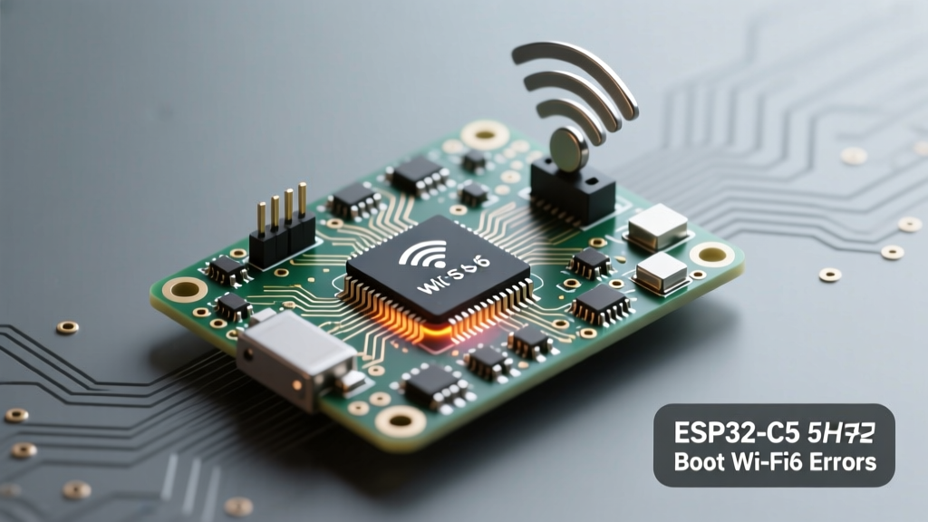
The introduction of the ESP32-C5 marks a significant paradigm shift in Espressif’s microcontroller lineup. Moving away from the Xtensa architecture, the C5 utilizes a single-core 32-bit RISC-V processor clocked at up to 240 MHz, paired with the highly anticipated Wi-Fi 6 (802.11ax) and dual-band 2.4 GHz / 5 GHz radio. While this provides massive improvements in Target Wake Time (TWT) and network efficiency, it also introduces an entirely new category of hardware and software anomalies.
For electrical engineers and advanced makers, diagnosing errors on the ESP32-C5 requires unlearning some assumptions carried over from the ESP32-S3 or ESP32-C3. The RISC-V rv32imc instruction set handles memory alignment and interrupt vectors differently, and the 5 GHz RF front-end demands significantly stricter power delivery and PCB impedance controls. When a C5 module fails, it rarely fails silently; instead, it throws specific RISC-V panic codes, bootloader loops, or RF calibration faults that require a targeted diagnostic approach.
Strapping Pin Conflicts and Bootloader Loops
One of the most frequent issues encountered during custom PCB design or breadboard prototyping with the ESP32-C5 is the dreaded boot loop. This occurs when the chip’s strapping pins are pulled to incorrect logic levels during the reset phase, forcing the silicon into unintended boot modes or incorrect internal voltage regulator states.
Unlike older generations, the ESP32-C5 relies on a specific set of GPIOs to determine the SPI boot source, the boot log output, and critically, the VDD_SPI voltage. If your external SPI flash or PSRAM requires 1.8V, but the strapping pin configures the internal LDO to 3.3V (or vice versa), the chip will immediately brownout or fail to read the bootloader, resulting in a continuous reset cycle.
ESP32-C5 Critical Strapping Pins
| GPIO Pin | Function | Logic 0 (Low) | Logic 1 (High) |
|---|---|---|---|
| GPIO8 | Boot Log Output | UART0 (Default Serial) | USB Serial/JTAG |
| GPIO9 | SPI Boot Source | SPI0 (Internal) | SPI1 (External) |
| GPIO10 | SPI Flash Mode | QIO / QOUT | DIO / DOUT |
| GPIO46 | VDD_SPI Voltage | 3.3V (Default) | 1.8V |
Diagnostic Fix: If your serial monitor outputs garbled text or nothing at all upon reset, check GPIO8. If it is being pulled high by an external circuit (like a sensor or MOSFET gate), the boot logs are being routed to the USB-JTAG peripheral instead of UART0. Ensure GPIO8 has a 10kΩ pull-down resistor for standard UART debugging. Furthermore, if you are using an external 1.8V SPI flash chip, GPIO46 must be pulled high; otherwise, the 3.3V output will fry the flash memory or trigger an immediate over-current protection reset.
Diagnosing Wi-Fi 6 (802.11ax) and 5GHz RF Failures
The ESP32-C5 is Espressif’s first foray into Wi-Fi 6 and 5 GHz connectivity. While 802.11ax offers superior OFDMA (Orthogonal Frequency-Division Multiple Access) handling, the 5 GHz band introduces severe RF attenuation and regulatory hurdles that manifest as connection drops or initialization failures in your Arduino sketches.
A common error in the ESP-IDF and Arduino Core v3.x environments is the WIFI_REASON_ASSOC_FAIL or WIFI_REASON_4WAY_HANDSHAKE_TIMEOUT when attempting to connect to a 5 GHz network. This is rarely a software bug; it is almost always a regulatory domain or DFS (Dynamic Frequency Selection) configuration error.
The DFS and Country Code Trap
In many global regions, 5 GHz channels (specifically between 5.25 GHz and 5.725 GHz) overlap with radar systems. The Wi-Fi 6 MAC layer on the C5 enforces strict DFS protocols. If your sdkconfig or Arduino WiFi initialization does not explicitly define the correct country code, the radio will refuse to transmit on 5 GHz channels to comply with FCC/CE regulations, resulting in silent association failures.
Pro-Tip: Always explicitly set the Wi-Fi country code in your initialization routine. Relying on the router's beacon frames to set the country code is unreliable in dual-band mesh networks and will cause the C5 to default to a safe, restricted channel map.
Furthermore, 5 GHz signals are highly susceptible to PCB trace impedance mismatches. If your custom PCB does not maintain a strict 50-ohm controlled impedance from the ESP32-C5 RF pin to the U.FL/IPEX connector or antenna, the Voltage Standing Wave Ratio (VSWR) will spike. The C5’s internal Power Amplifier (PA) will detect this mismatch during the RF calibration phase at boot, leading to a PHY_INIT: RF calibration failed panic. According to the Espressif Hardware Design Guidelines, a pi-type matching network is mandatory for 5 GHz designs to compensate for parasitic capacitance.
Power Delivery: Surviving the 5GHz TX Current Spikes
Hardware engineers migrating from the ESP32-C3 to the C5 often reuse their existing power supply circuits, only to encounter the infamous rst:0xf (BROWNOUT_RST) error code. Transmitting on the 5 GHz band requires significantly more power than the 2.4 GHz band. During a Wi-Fi 6 TX burst, the ESP32-C5’s internal PA can draw transient current spikes exceeding 380 mA to 420 mA.
If your LDO (Low Dropout Regulator) is rated for 500 mA but has a slow transient response, or if your PCB power traces are too thin (causing excessive voltage droop due to resistance), the internal voltage rail will dip below the Brownout Detector (BOD) threshold (typically around 2.4V on the main VDD rail). The BOD instantly resets the chip to prevent silicon latch-up and memory corruption.
Power Supply Decoupling Framework
- Bulk Capacitance: Place a minimum 22µF low-ESR ceramic capacitor (X5R or X7R) as close to the VDD pin as possible. Do not rely solely on electrolytic capacitors, as their ESL (Equivalent Series Inductance) is too high to respond to microsecond RF bursts.
- High-Frequency Decoupling: Add a 100nF and a 10nF capacitor in parallel near the VDD_RTC and VDD_CPU pins to filter out high-frequency RISC-V switching noise.
- LDO Selection: Use an LDO with a transient response time of less than 5µs and a maximum dropout voltage of 200mV at 500mA. The AMS1117 is not recommended for C5 5GHz applications due to its poor transient response and high dropout.
ESP-IDF and Arduino Core Toolchain Mismatches
Because the ESP32-C5 utilizes a RISC-V architecture and requires Wi-Fi 6 MAC layer support, it is entirely unsupported in legacy Arduino ESP32 cores (v2.x) and ESP-IDF versions prior to v5.2. Attempting to compile C5 code on outdated toolchains will result in riscv32-esp-elf-gcc: error: unrecognized command-line option or missing header files like esp_wifi_types.h.
When using the Arduino IDE 2.x, you must ensure you are utilizing the ESP32 Arduino Core v3.0.0 or newer. The underlying ESP-IDF framework introduced a unified Wi-Fi driver (esp_wifi) that handles 802.11ax specific parameters like TWT and MU-MIMO. If you are porting code from an ESP32-S3, you will likely encounter compilation errors regarding deprecated Wi-Fi event macros. The Espressif Wi-Fi API Guide details the new event structures required for Wi-Fi 6 negotiation.
Additionally, memory allocation errors such as Core 0 panic'ed (Load access fault) frequently occur when developers attempt to execute Wi-Fi 6 stack functions from standard DRAM instead of IRAM. The RISC-V memory protection unit (MPU) on the C5 is stricter than the Xtensa MMU. Ensure that any custom interrupt service routines (ISRs) handling RF events are tagged with IRAM_ATTR and that memory is allocated using heap_caps_malloc(size, MALLOC_CAP_EXEC) when dealing with executable code blocks.
Diagnostic Flowchart for C5 Silicon Anomalies
Use the following structured diagnostic matrix to quickly isolate the root cause of your ESP32-C5 failures. This framework prioritizes hardware and PHY-layer checks before diving into software stack debugging.
| Observed Symptom | Serial Monitor Output / Error Code | Root Cause Category | Corrective Action |
|---|---|---|---|
| Continuous reboot loop, no serial output | Gibberish or Silence at 115200 baud | Strapping Pin / VDD_SPI | Verify GPIO8 (UART routing) and GPIO46 (Flash voltage). Check 3.3V rail stability. |
| Reboots exactly when Wi-Fi connects | rst:0xf (BROWNOUT_RST) |
Power Delivery / TX Spike | Upgrade LDO, add 22µF X7R MLCC, check trace width for VDD rail. |
| 5GHz Network not found / Association fails | WIFI_REASON_ASSOC_FAIL |
Regulatory / DFS Config | Hardcode Wi-Fi Country Code in esp_wifi_set_country(). Verify router channel. |
| Boot panic during RF Init | PHY_INIT: RF calibration failed |
Antenna Mismatch / VSWR | Check 50-ohm trace impedance. Ensure pi-match network components are populated. |
| Random crashes during high network traffic | Core 0 panic'ed (Load access fault) |
Memory Protection / ISR | Add IRAM_ATTR to ISRs. Verify PSRAM clock limits (max 80MHz on C5). |
Final Thoughts on C5 Integration
The ESP32-C5 is a formidable leap forward for IoT devices requiring high-throughput, low-latency wireless communication. However, its dual-band Wi-Fi 6 capabilities and RISC-V core demand a much higher standard of electrical design and firmware configuration. By systematically addressing strapping pin logic, enforcing strict 5GHz RF impedance controls, and ensuring robust transient power delivery, you can eliminate the vast majority of boot and connectivity errors. Always refer to the latest Arduino-ESP32 GitHub repository for core updates, as Wi-Fi 6 stack optimizations and RISC-V compiler patches are actively being pushed to resolve edge-case silicon anomalies.