
The Paradigm Shift: Why Espressif Built the ESP32-C3
For nearly a decade, the ESP8266 was the undisputed king of low-cost IoT prototyping. However, as security requirements tightened and Bluetooth Low Energy (BLE) became a baseline expectation for smart home devices, the aging Xtensa architecture of the ESP8266 reached its limits. Enter the ESP32-C3. Released as a direct, modern successor to the ESP8266, the ESP32-C3 represents a massive architectural pivot for Espressif: it abandons the proprietary Xtensa instruction set in favor of the open-standard RISC-V architecture.
For makers and embedded engineers, the ESP32-C3 is not just a faster ESP8266; it is a fundamentally different beast. It bridges the gap between ultra-low-cost sensor nodes and the high-performance, but more expensive, ESP32-S3. In this concept explainer, we will dissect the ESP32-C3's silicon, explore its unique hardware peripherals, and outline the specific failure modes you must avoid when designing your next PCB or wiring up a dev board.
Under the Silicon: RISC-V vs. Xtensa
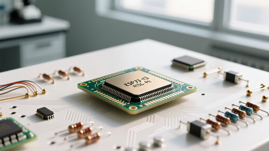
The most critical concept to understand about the ESP32-C3 is its core. Unlike the original ESP32 or the ESP32-S2 (which use Tensilica Xtensa cores), the ESP32-C3 utilizes a 32-bit RISC-V single-core microcontroller running at up to 160 MHz. According to the RISC-V International Foundation, this open-standard Instruction Set Architecture (ISA) eliminates the licensing fees associated with proprietary cores, allowing Espressif to pass the savings directly to the consumer.
From a compiler perspective, this means the GCC toolchain used for the ESP32-C3 is standard RISC-V, making it easier for the open-source community to maintain and optimize. However, for developers writing inline assembly or relying on highly optimized, legacy Xtensa DSP libraries, the transition requires a complete rewrite. The single-core design also means you do not have the dual-core luxury of the classic ESP32, where one core handles Wi-Fi/BT stacks while the other handles application logic. On the C3, the FreeRTOS scheduler must seamlessly time-slice the RF stack and your user code on the same core.
Deep Dive: Technical Specifications and Comparisons
To understand where the ESP32-C3 fits in the maker ecosystem, we must compare it against its predecessor (ESP8266) and its bigger sibling (ESP32-S3). The following table highlights the critical hardware differences that dictate project selection.
| Feature | ESP8266 (Legacy) | ESP32-C3 (Modern IoT) | ESP32-S3 (High-Perf) |
|---|---|---|---|
| Core Architecture | Xtensa L106 (Single) | RISC-V (Single, 160MHz) | Xtensa LX7 (Dual, 240MHz) |
| Wireless | Wi-Fi 4 | Wi-Fi 4 + BLE 5.0 | Wi-Fi 4 + BLE 5.0 |
| SRAM | ~50 KB usable | 400 KB | 512 KB |
| GPIO Count | 17 (Many restricted) | 22 (Highly flexible) | 45 |
| USB Peripheral | None (Requires UART) | USB Serial/JTAG | USB OTG + Serial/JTAG |
| Capacitive Touch | No | No | Yes (14 channels) |
| Typical Bare Chip Cost | ~$1.50 | ~$1.10 | ~$2.80 |
As detailed in the Espressif ESP32-C3 official documentation, the 400KB of internal SRAM is a massive leap from the ESP8266, easily accommodating complex TLS handshakes and modern JSON parsing libraries without requiring external PSRAM (which the C3 does not support natively).
Hardware Design Realities: The USB-Serial-JTAG Peripheral
One of the most transformative features of the ESP32-C3 is the integrated USB Serial/JTAG controller. In older designs, a dedicated USB-to-UART bridge chip (like the CP2102 or CH340) was mandatory for programming and debugging. This added BOM cost, PCB real estate, and power consumption.
The ESP32-C3 routes its USB D+ and D- lines directly to GPIO18 and GPIO19. This allows you to plug the chip directly into a USB port for flashing and serial monitoring. Furthermore, the JTAG capability means you can perform hardware-level debugging (setting breakpoints, stepping through memory) using OpenOCD over the exact same USB connection, without needing a specialized external debugger.
The 'SuperMini' Dev Board Caveat
If you have purchased the ubiquitous, ultra-cheap 'ESP32-C3-SuperMini' boards from online marketplaces, be aware of a specific hardware quirk. To keep the board footprint minuscule, manufacturers often omit the necessary RF shielding and use suboptimal trace routing for the 2.4GHz antenna. While perfectly fine for bench testing, these specific boards can suffer from a 10-15dBm drop in Wi-Fi transmission power compared to the official ESP32-C3-DevKitM-1. For deployed, in-wall IoT sensors, always opt for boards with a certified IPEX connector or a properly tuned PCB trace antenna.
Real-World Failure Modes and Strapping Pin Quirks
The ESP32-C3 is highly reliable, but improper handling of its strapping pins during boot will lead to immediate failure. Unlike classic microcontrollers that simply boot from flash, the C3 samples specific GPIOs during the reset phase to determine its boot mode.
Expert Warning: If your ESP32-C3 is stuck in a boot loop or failing to flash via the Arduino IDE, check your wiring on GPIO2, GPIO8, and GPIO9. Pulling these pins to the wrong logic level during power-on will force the chip into unintended ROM bootloaders or SPI test modes.
- GPIO8: Controls the boot source. Must be HIGH (or floating with internal pull-up) to boot from SPI Flash. If pulled LOW, it attempts to boot from the USB interface.
- GPIO9: Determines the log output. If pulled LOW, boot logs are printed to the USB Serial/JTAG. If HIGH, they route to UART0.
- GPIO2: Used for factory test mode. Must be LOW or floating during normal boot.
Another common failure mode involves the ADC (Analog-to-Digital Converter). The ESP32-C3 features a 12-bit SAR ADC, but due to internal noise floors and non-linearity at the extremes of the voltage rail, practical resolution is closer to 10 bits. If you are designing a precision sensor node, do not rely on the internal ADC for sub-millivolt measurements; use an external I2C ADC like the ADS1115.
Software Ecosystem: Arduino Core and ESP-IDF
Because the ESP32-C3 uses a standard RISC-V core, it is fully supported by the official Espressif Arduino Core. To get started, makers simply need to add the Espressif board manager URL to the Arduino IDE, select the 'ESP32C3 Dev Module', and compile. The underlying FreeRTOS handles the Wi-Fi and BLE stacks invisibly in the background.
However, for commercial deployments, the ESP-IDF (IoT Development Framework) is highly recommended. The ESP-IDF unlocks the ESP32-C3's advanced security features, which are largely abstracted away in the Arduino environment.
Flash Encryption and Secure Boot v2
The C3 includes a hardware RSA-3072 accelerator and an AES-128/256 accelerator. This enables Secure Boot v2 and Flash Encryption. By burning eFuses (one-time programmable memory), you can cryptographically sign your firmware and encrypt the SPI flash contents. This ensures that even if a malicious actor desolders the flash chip, they cannot read your proprietary code or Wi-Fi credentials, and they cannot flash unauthorized firmware onto your device.
The Decision Framework: When to Choose the ESP32-C3
Selecting the right microcontroller is about matching silicon capabilities to project constraints. Use this framework to determine if the ESP32-C3 is the right fit for your build:
Choose the ESP32-C3 When:
- Cost and Space are Critical: You need a Wi-Fi/BLE node that fits in a tiny enclosure (like a smart plug or light switch) and costs under $2 in volume.
- ESP8266 Migration: You are updating legacy ESP8266 codebases and need more RAM, better security, and BLE support without moving to a dual-core architecture.
- Simple Sensor Telemetry: Your device reads I2C/SPI sensors and pushes data to MQTT or a cloud REST API.
Avoid the ESP32-C3 When:
- High-Throughput Data: You need to interface with a camera module (the C3 lacks the LCD/Camera interfaces of the S3) or stream high-fidelity I2S audio.
- Capacitive Touch Interfaces: You are building a touch-sensitive UI panel (the C3 does not have the touch sensor peripheral found on the classic ESP32).
- Heavy DSP Requirements: Your application requires real-time audio processing or complex vector math, which benefits heavily from the dual-core and vector instructions of the ESP32-S3.
By understanding the RISC-V foundation, the USB-JTAG hardware benefits, and the strict strapping pin requirements, you can leverage the ESP32-C3 to build highly secure, cost-effective, and modern IoT devices that leave the legacy ESP8266 firmly in the past.