
The 3.3V Logic Hurdle: Voltage Level Translation
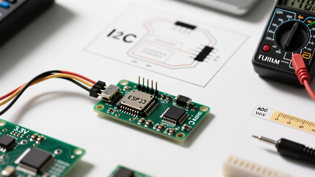
Transitioning from legacy 5V AVR microcontrollers to an ESP microcontroller (such as the ESP8266, ESP32, or the newer RISC-V based ESP32-C3) introduces an immediate hardware compatibility hurdle: logic voltage levels. While the classic ATmega328P operates comfortably at 5V and generally tolerates 3.3V inputs, Espressif's silicon is strictly 3.3V tolerant. Feeding a 5V signal directly into an ESP32 GPIO pin will degrade the silicon over time or cause catastrophic latch-up failure.
When integrating 5V sensors, relays, or legacy Arduino shields, you must implement voltage translation. However, not all logic level shifters are created equal, and choosing the wrong one is a primary cause of I2C and SPI bus failures in maker projects.
Why the TXS0108E Fails on I2C Buses
Many commercial bi-directional logic level shifter modules utilize the Texas Instruments TXS0108E chip. While excellent for high-speed SPI or UART, the TXS0108E is notoriously problematic for I2C. The chip features internal 10kΩ pull-up resistors and one-shot edge accelerators. When combined with the standard 4.7kΩ external pull-ups required by most 5V I2C sensor breakout boards, the parallel resistance drops, and the internal edge-acceleration circuitry fights the I2C open-drain architecture, resulting in corrupted data packets and bus lockups.
For reliable I2C translation between a 5V sensor and an ESP microcontroller, use discrete BSS138 MOSFET-based shifters. These lack internal pull-ups and edge accelerators, perfectly preserving the open-drain nature of the I2C bus. For unidirectional signals (like a 5V SPI MISO line feeding into the ESP32), a simple CD4050BE non-inverting buffer powered at 3.3V is both cheaper and highly effective.
| Shifter Component | Best Use Case | I2C Safe? | Approx. Cost |
|---|---|---|---|
| BSS138 MOSFET Module | I2C, 1-Wire, Low-speed UART | Yes | $0.80 |
| TXS0108E IC | High-speed SPI, SD Cards | No | $1.50 |
| CD4050BE Buffer | Unidirectional (5V to 3.3V) | Yes | $0.50 |
| Voltage Divider (Resistors) | UART RX, simple digital out | No (Capacitance issues) | $0.05 |
Pinout Mapping: Why Arduino Shields Fail on ESP Boards
The physical footprint of an ESP32 DevKit or ESP8266 NodeMCU does not align with the standard Arduino Uno R3 shield header spacing. Even if you wire an Arduino shield manually via jumper wires, you will encounter a secondary compatibility issue: hardcoded SPI and I2C pin mappings in legacy Arduino libraries.
In the AVR ecosystem, the SPI hardware pins are fixed (MOSI on 11, MISO on 12, SCK on 13). On an ESP microcontroller, the GPIO matrix allows almost any pin to be mapped to the SPI or I2C peripherals via software. However, many older libraries assume the AVR pinout. To force compatibility, you must explicitly reassign the buses in your setup function.
SPI Bus Reassignment Strategy
When connecting an SPI-based display (like the ILI9341) or an SD card module to an ESP32, avoid the default hardware strapping pins (like GPIO 12, which can cause boot failures if pulled high). Instead, map the SPI bus to safe GPIOs using the ESP32 Arduino Core's extended SPI class:
// ESP32 SPI Remapping Example
#define SCK_PIN  18
#define MISO_PIN 19
#define MOSI_PIN 23
#define SS_PIN   5

void setup() {
  SPI.begin(SCK_PIN, MISO_PIN, MOSI_PIN, SS_PIN);
  // Initialize your SPI device here
}
I2C Bus Reassignment and Pull-Up Rules
The default I2C pins on the original ESP32 are GPIO 21 (SDA) and GPIO 22 (SCL). However, if you migrate to the newer ESP32-S3 or ESP32-C3, these default pins change entirely (e.g., GPIO 8 and 9 on the S3). Always use the Wire.setPins(sda, scl) function before calling Wire.begin() to ensure your code remains hardware-agnostic across the ESP family. Furthermore, if you are running the I2C bus at 400kHz (Fast Mode) over wires longer than 15cm, drop your pull-up resistors from 4.7kΩ to 2.2kΩ to overcome the parasitic capacitance of the ESP32's GPIO pads.
Analog-to-Digital Converter (ADC) Incompatibilities
Perhaps the most misunderstood aspect of ESP microcontroller compatibility is the Analog-to-Digital Converter. Makers frequently attempt to port 5V analog sensor code directly to the ESP8266 or ESP32, resulting in fried pins or wildly inaccurate readings.
ESP8266 vs. ESP32 ADC Real-World Limits
The ESP8266 features a single ADC channel (A0) with a 10-bit resolution. Critically, the maximum input voltage on the ESP8266 A0 pin is 1.0V. Connecting a standard 3.3V or 5V analog sensor directly to this pin will destroy the internal ADC circuitry. You must use a voltage divider (e.g., 220kΩ and 100kΩ) to scale a 3.3V signal down to ~1.0V.
The ESP32 improves upon this with multiple 12-bit ADC channels and an internal programmable attenuator. By setting the attenuation to 11dB (analogSetPinAttenuation(pin, ADC_11db)), the ESP32 can safely read voltages up to ~3.3V. However, the ESP32's internal ADC is notoriously non-linear at the extreme bottom (0 - 0.15V) and top (3.1V - 3.3V) of its range. If your project requires precision analog readings (such as load cells or precision NTC thermistors), bypass the ESP microcontroller's internal ADC entirely and use an external I2C ADC like the ADS1115.
| MCU / Chip | Resolution | Max Safe Voltage | Linearity & Noise |
|---|---|---|---|
| ESP8266 (A0) | 10-bit | 1.0V (Strict Limit) | Poor, high noise floor |
| ESP32 (ADC1) | 12-bit | 3.3V (with 11dB atten) | Non-linear at 0V and 3.3V edges |
| ADS1115 (External) | 16-bit | 3.3V / 5V (VDD dependent) | Excellent, PGA equipped |
Power Delivery: Brownouts and RF Transmission Spikes
A common failure mode when integrating ESP microcontrollers into sensor networks is the 'random reboot' syndrome. This is rarely a software bug; it is almost always a power delivery incompatibility. When the ESP32's Wi-Fi or Bluetooth radio transmits, the current draw can spike from a baseline of 80mA to over 500mA for brief milliseconds.
If you are powering the ESP32 via a breadboard using thin 24AWG jumper wires from a standard 500mA USB wall adapter, the inductance and resistance of the breadboard rails will cause a voltage sag. If the 3.3V regulator on the DevKit drops below 2.8V during an RF spike, the ESP32's internal brownout detector (BOD) will trigger a hard reset.
Expert Troubleshooting Tip: To solve RF brownouts without upgrading your entire power supply, solder a 470µF to 1000µF electrolytic capacitor directly across the VIN and GND pins on the ESP32 DevKit. This acts as a local energy reservoir, absorbing the microsecond current spikes that thin jumper wires cannot deliver. For detailed power layout recommendations, consult the Espressif Hardware Design Guidelines.
Software Ecosystem: Arduino IDE 2.x and Framework Compatibility
Hardware compatibility is only half the battle. The software ecosystem for the ESP microcontroller family has undergone massive shifts, particularly with the release of the Arduino ESP32 Core v3.0 and above. Code written for the legacy v1.x or v2.x cores will frequently fail to compile on modern setups.
Breaking Changes in the Modern ESP32 Core
- analogReadMilliVolts(): Because of the ESP32's ADC non-linearity mentioned earlier, the standard
analogRead()function is being phased out for precision work. The modern core introducesanalogReadMilliVolts(), which utilizes the chip's internal eFuse calibration data to return a highly accurate, linearized voltage reading in millivolts. - I2C Driver Overhaul: The underlying ESP-IDF framework updated the I2C driver, meaning older libraries that relied on direct register manipulation (common in high-speed display drivers) will now throw compilation errors. You must use the standard
WireAPI or update to libraries that support the newi2c_masterESP-IDF API. - Board Manager URLs: Ensure your Arduino IDE 2.x preferences include the official Espressif JSON URL. Relying on outdated third-party board manager links will result in missing RISC-V toolchain dependencies for the ESP32-C3 and C6 variants.
For the most up-to-date compatibility matrices and core installation instructions, always refer to the official Espressif Arduino Core GitHub Repository. By understanding the physical, electrical, and software boundaries of the ESP microcontroller family, you can seamlessly integrate modern Wi-Fi and BLE capabilities into your existing sensor ecosystems without falling victim to the common pitfalls of 3.3V migration.