
The Hidden Cost of Convenience: 9V Batteries and Linear Regulators
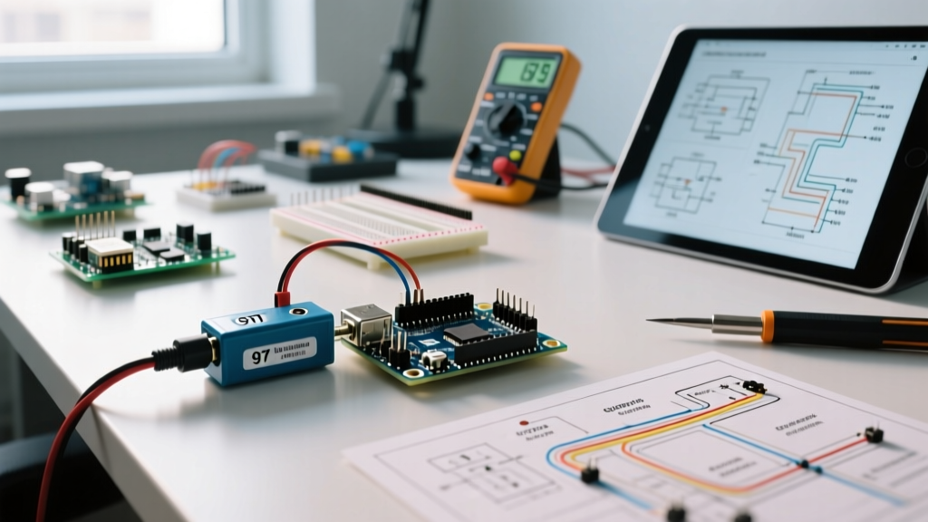
For decades, the standard initiation into physical computing involved snapping a 9V alkaline battery to a barrel jack and plugging it into an Arduino Uno. While this 9 volt battery Arduino workflow is unmatched for rapid breadboard prototyping, it is notoriously inefficient for deployed applications. To optimize your power workflow in 2026, you must first understand the thermal and electrical bottlenecks of the onboard linear regulator.
Most standard Arduino boards (like the Uno R3 and Nano) utilize an NCP1117ST50T3G or similar 5V Low Dropout (LDO) linear regulator. Linear regulators operate by burning off excess voltage as heat. When you supply 9V to the barrel jack, the regulator drops it to 5V. The power dissipated is calculated as P = (Vin - Vout) × I_load. If your circuit draws just 50mA, the regulator wastes 200mW as heat. More critically, the regulator draws the exact same current from the 9V source as it supplies to the 5V rail. A standard Energizer MAX 9V alkaline battery holds roughly 550mAh. At a continuous 50mA draw, your theoretical maximum runtime is a mere 11 hours—assuming the battery voltage doesn't sag below the regulator's dropout threshold first.
Battery Chemistry Matrix: 9V vs. Modern Alternatives
Optimizing your workflow means knowing exactly when to use a 9V battery and when to migrate to higher-density chemistries. The table below outlines the practical trade-offs for maker projects in 2026.
| Battery Type | Nominal Voltage | Typical Capacity | Avg Cost (2026) | Optimal Workflow Stage |
|---|---|---|---|---|
| 9V Alkaline (e.g., Energizer MAX) | 9V | ~550 mAh | $3.50 | Rapid Prototyping / Bench Testing |
| 9V Lithium (e.g., Energizer Ultimate) | 9V | ~1,000 mAh | $8.00 | Short-term Deployments / Cold Weather |
| 18650 Li-Ion (e.g., Molicel P26A) | 3.7V | ~2,600 mAh | $6.50 | Long-term Deployment / High Current |
| 3S LiPo (11.1V) | 11.1V | ~2,200 mAh | $22.00 | Robotics / High-Draw Servos |
Hardware Workflow: Bypassing the Onboard LDO Bottleneck
If your project constraints dictate the use of a 9V form factor (such as fitting into a specific legacy enclosure), you must bypass the inefficient onboard LDO to achieve acceptable battery life. The most effective hardware optimization is integrating a switching buck converter.
By utilizing a high-efficiency step-down regulator like the Pololu D24V5ALF, you convert the 9V input to 5V using pulse-width modulation rather than thermal dissipation. Switching regulators can achieve 80% to 90% efficiency. Because power is conserved (minus conversion losses), the current drawn from the 9V battery is significantly lower than the current supplied to the 5V rail. Furthermore, the Pololu D24V5ALF features a low quiescent current draw, meaning it won't drain your battery when the microcontroller enters sleep mode.
Expert Workflow Tip: Never connect a switching regulator directly to the Arduino's 5V pin if you are also connected to USB. Backfeeding voltage into the 5V rail while the USB port is active can damage your computer's USB controller or the Arduino's polyfuse. Always use a DPDT switch to isolate the battery circuit during serial debugging.
Software Workflow: Squeezing Microamps via AVR Sleep Modes
Hardware optimization only solves half the equation. The ATmega328P microcontroller at the heart of most standard Arduinos is capable of incredible power efficiency, but the default Arduino core keeps all peripherals active. To optimize a 9 volt battery Arduino setup for long-term sensor logging, you must implement AVR sleep modes.
The Rocket Scream Low-Power library provides an accessible wrapper for the native AVR sleep commands. By disabling the Analog-to-Digital Converter (ADC) and the Brown-Out Detector (BOD), and putting the CPU into POWER_DOWN mode, you can reduce the microcontroller's current draw from ~15mA to roughly 0.1µA.
Implementation Example: Periodic Sensor Logging
#include <LowPower.h>

const int sensorPin = A0;
int sensorValue = 0;

void setup() {
  // Disable the ADC to save approximately 300µA
  ADCSRA &= ~(1 << ADEN);
  pinMode(LED_BUILTIN, OUTPUT);
}

void loop() {
  // Wake up: Re-enable ADC temporarily
  ADCSRA |= (1 << ADEN);
  sensorValue = analogRead(sensorPin);

  // Transmit data or write to SD card here
  transmitData(sensorValue);

  // Disable ADC again before sleeping
  ADCSRA &= ~(1 << ADEN);

  // Enter power-down sleep for 8 seconds (ADC and BOD off)
  LowPower.powerDown(SLEEP_8S, ADC_OFF, BOD_OFF);
}
According to the Microchip ATmega328P datasheet, the power-down mode with BOD disabled yields the lowest possible current consumption. When paired with a switching regulator, a standard 9V alkaline battery can power this sleep-cycling workflow for several months, rather than hours.
The Prototyping-to-Deployment Pipeline
A mature engineering workflow treats the 9V battery as a temporary prototyping tool, not a final deployment solution. Here is a standardized pipeline to transition your project from the workbench to the field:
- Phase 1: Breadboard Validation (Days 1-3): Use a standard 9V alkaline battery connected to the Vin pin. Focus purely on logic validation, sensor calibration, and serial debugging. Do not worry about power consumption.
- Phase 2: Current Profiling (Day 4): Insert a multimeter in series with the battery ground. Measure the active current draw and the sleep current. If your sleep current is above 1mA, audit your code and external modules (e.g., I2C sensors pulling idle current).
- Phase 3: Regulator Migration (Day 5): Move from the onboard LDO to an external buck converter on a perfboard or custom PCB. Verify the switching frequency isn't introducing noise into your analog sensor readings.
- Phase 4: Final Power Source (Deployment): Migrate to a 3.7V LiPo or 18650 cell. If your circuit is strictly 3.3V logic, bypass the 5V regulator entirely and use a 3.3V LDO or buck-boost converter to maximize the lithium cell's discharge curve.
Real-World Failure Mode: Servo Brownouts and Voltage Sag
The most common point of failure when mixing a 9 volt battery Arduino setup with actuators is voltage sag. A standard micro servo (like the ubiquitous SG90) can draw upwards of 700mA during stall or startup conditions.
A fresh 9V alkaline battery has an internal resistance of approximately 1.5 to 2.0 ohms. Applying Ohm's Law (V = I × R), a 700mA current spike causes a voltage drop of 1.05V to 1.4V inside the battery itself. If your battery is partially depleted and sitting at 7.5V, that servo spike will drag the terminal voltage down to ~6.1V. This falls dangerously close to the dropout voltage of the NCP1117 regulator, causing the 5V rail to collapse. The ATmega328P's internal Brown-Out Detector (BOD) will trigger at 4.3V, instantly resetting your microcontroller and corrupting any data being written to non-volatile memory.
The Fix: Never power servos directly from the Arduino's 5V pin when using a 9V battery. Use a separate voltage regulator for the servos, and add a large decoupling capacitor (e.g., 1000µF electrolytic) across the servo's power rails to buffer transient current spikes and protect the logic rail from collapsing.
Summary
Mastering the 9 volt battery Arduino workflow requires moving beyond the plug-and-play mindset. By acknowledging the thermal limits of linear regulators, leveraging switching converters, and aggressively utilizing AVR sleep modes, you can transform a notoriously weak power source into a viable solution for low-duty-cycle embedded systems.