
The canonical 'Blink' sketch is the definitive baseline test for any microcontroller workflow. When a standard blink in arduino fails, it is rarely a coding error; rather, it exposes deep fractures in your toolchain, bootloader integrity, or hardware routing. As of 2026, with the proliferation of Arduino Uno R4 variants and advanced ESP32-C3 boards, diagnosing a failed Blink requires a systematic approach that goes far beyond simply checking the USB cable.
This guide provides a senior-level diagnostic framework for isolating compilation mismatches, avrdude synchronization failures, and physical GPIO faults when your onboard LED refuses to flash.
Phase 1: Compilation and Macro Mapping Errors
Before an upload error can occur, the code must compile. The Blink sketch relies heavily on the LED_BUILTIN macro. If your code compiles and uploads successfully, but the physical LED does not blink, you are likely facing a macro-mapping mismatch.
The LED_BUILTIN Abstraction Trap
In the legacy Arduino Uno R3 (ATmega328P), LED_BUILTIN is hardcoded to Pin 13. However, modern maker ecosystems have fragmented this standard:
- Arduino Uno R4 Minima: Uses the Renesas RA4M1 ARM Cortex-M4. While
LED_BUILTINmaps to Pin 13, the underlying HAL (Hardware Abstraction Layer) handles the GPIO toggle differently. Direct port manipulation (e.g.,PORTB |= (1 << 5)) will fail to blink the LED on the R4. - ESP32-C3 SuperMini: A highly popular $3.50 clone board in 2026. The onboard RGB LED (WS2812) is often tied to Pin 8, while a standard secondary status LED might be on Pin 10. Using the standard Blink sketch without modifying the pin definition will result in a dark board.
- ATmega328P-PU (DIP-28) Custom Boards: If you are programming a raw chip on a breadboard, Pin 13 corresponds to physical pin 19 on the IC. If wired incorrectly to the wrong physical leg, the software will execute flawlessly while the hardware remains inert.
Diagnostic Action: Always verify the pinout schematic for your specific board revision. If using a clone board, upload a sketch that sequentially toggles Pins 8 through 13 to physically locate the active LED GPIO.
Phase 2: Diagnosing the 'avrdude: stk500_getsync()' Error
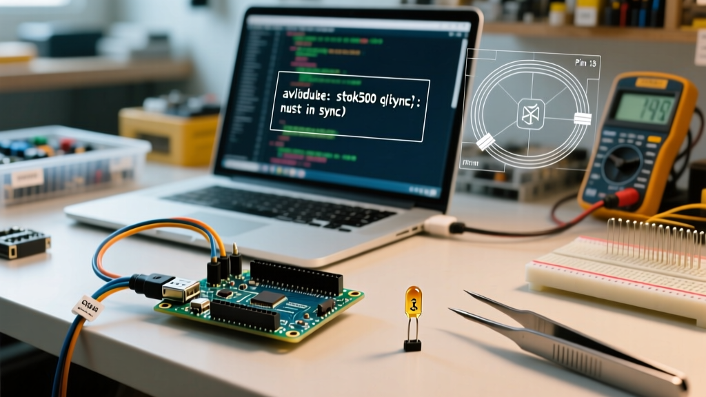
The most common point of failure when attempting to upload a blink in arduino is the synchronization error. The IDE console will repeatedly output:
avrdude: stk500_getsync() attempt 10 of 10: not in sync: resp=0x00This error means the host PC cannot establish a serial handshake with the ATmega bootloader. According to the official Arduino IDE troubleshooting documentation, this is typically a breakdown in the auto-reset circuit or a driver conflict.
The Auto-Reset Circuit Failure
On standard Uno and Nano boards, the USB-to-Serial chip (ATmega16U2, CH340G, or CP2102) uses the DTR (Data Terminal Ready) or RTS (Request to Send) line to trigger a hardware reset. This signal is routed through a 0.1µF coupling capacitor to the ATmega328P's RESET pin.
Failure Mode: On budget clone boards (often priced between $4.00 and $6.00), this SMD capacitor is frequently defective, misaligned, or suffers from cold solder joints. When the capacitor fails, the DTR pulse never reaches the RESET pin. The bootloader never wakes up, and avrdude times out.
Diagnostic Steps for Sync Errors
- The Manual Reset Test: Press and hold the physical RESET button on the board. Click 'Upload' in the IDE. The moment the console reads
Sketch uses X bytes, release the RESET button. If the upload succeeds, your 0.1µF auto-reset capacitor is dead. - Driver Verification (Windows 11): If your board uses the CH340G or CH340C chip, Windows 11 may silently install an unsigned, incompatible legacy driver. You must manually force-install the WCH signed drivers. Refer to the SparkFun CH340 Driver Guide for the exact INF file selection process.
- Logic Analyzer Probe: Connect a $10 USB logic analyzer to the TX, RX, and RESET pins. Trigger on the DTR line dropping low. If DTR drops but RESET does not follow within 2 milliseconds, the trace or capacitor is broken.
Phase 3: Hardware and Pin 13 LED Diagnostics
Suppose your code compiles, the upload completes with 'Done uploading', the console reports no errors, but the onboard LED remains completely dark. You are now in the hardware diagnostic phase.
The LMV358 Op-Amp Buffer Quirk
Many makers do not realize that on the official Arduino Uno R3, Pin 13 does not directly drive the onboard 'L' LED. Because Pin 13 is also the hardware SPI SCK (Clock) line, drawing too much current from an LED would corrupt SPI communications with shields and SD card modules.
To solve this, Arduino engineers placed an LMV358 dual operational amplifier on the board. Pin 13 feeds into the non-inverting input of the op-amp, which then drives the LED through a 1kΩ resistor.
Multimeter Troubleshooting Matrix
Use a high-impedance multimeter (like a Fluke 117) to probe the board while the blink in arduino sketch is running. Set your meter to DC Voltage and measure the following nodes:
| Measurement Node | Expected Reading (Blink HIGH) | Expected Reading (Blink LOW) | Diagnosis if Abnormal |
|---|---|---|---|
| ATmega328P Pin 19 (SCK) | ~5.0V | ~0.0V | MCU is dead or sketch is halted in a while(1) loop. |
| LMV358 Pin 3 (Input) | ~5.0V | ~0.0V | Trace between MCU and Op-Amp is severed. |
| LMV358 Pin 1 (Output) | ~4.8V | ~0.1V | Op-Amp is functional; issue is downstream. |
| LED Anode (Post-Resistor) | ~3.2V | ~0.0V | LED is blown (open circuit) or solder pad lifted. |
If the LMV358 output (Pin 1) is toggling correctly, but the LED remains dark, the 1kΩ current-limiting resistor is likely blown (often caused by a user accidentally shorting the LED header to 5V in a previous project), or the LED itself has suffered thermal catastrophic failure.
Advanced Edge Case: Bootloader Corruption
If you have ruled out USB drivers, auto-reset capacitors, and physical LED damage, the ATmega328P's flash memory may have lost the Optiboot bootloader. This frequently happens if a sketch utilizes direct memory pointers or if the board experienced a brownout during a previous flash cycle.
When the bootloader is corrupted, the chip will execute whatever is in memory (or hang at address 0x0000), but it will never listen for the serial handshake required to upload a new blink in arduino sketch.
Restoring the Bootloader via ISP
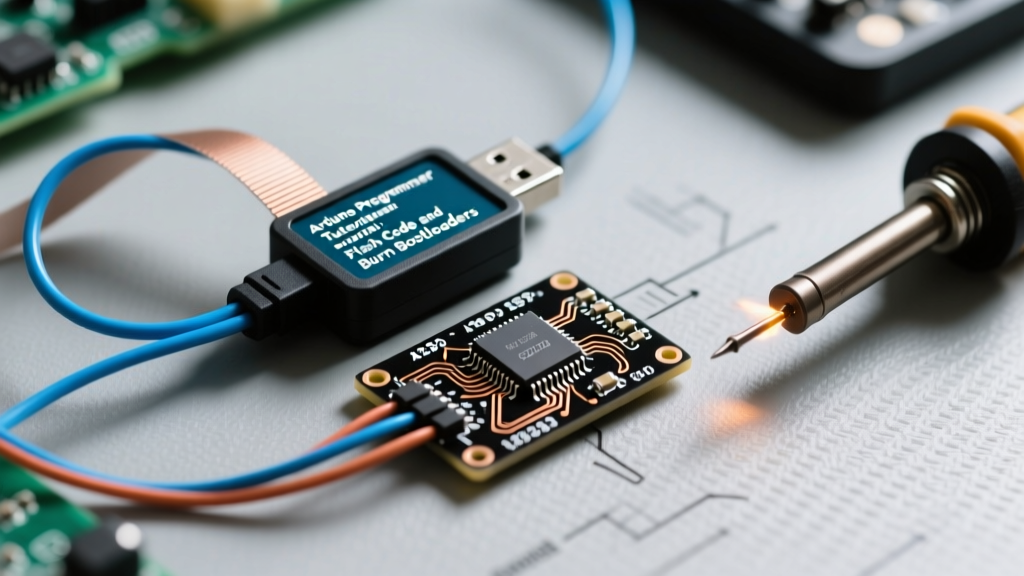
To fix this, you must bypass the USB-Serial chip entirely and use the ICSP (In-Circuit Serial Programming) header. As detailed in the legendary Nick Gammon bootloader programming guide, you can use a second working Arduino as an ISP (In-System Programmer).
- Flash the 'ArduinoISP' sketch onto your working donor board.
- Wire the donor board's Pins 10, 11, 12, and 13 to the target board's RESET, MOSI, MISO, and SCK pins, respectively.
- In the IDE, select Tools > Programmer > Arduino as ISP.
- Click Tools > Burn Bootloader.
This process takes approximately 15 seconds. It will erase the corrupted flash, write the fresh Optiboot hex file to the uppermost 512 bytes of memory, and set the correct fuse bits (specifically setting the BOOTRST fuse so the chip jumps to the bootloader on power-up). Once complete, your board will instantly accept standard USB uploads again.
Summary Checklist for 2026 Maker Workbenches
When diagnosing a failed Blink sketch, resist the urge to immediately blame the IDE. Follow the signal path logically:
- Verify the Macro: Ensure
LED_BUILTINmatches your specific silicon (especially on ESP32 and ARM Cortex variants). - Test the Auto-Reset: Use the manual RESET button timing trick to rule out a blown 0.1µF coupling capacitor.
- Probe the Hardware: Use a multimeter to check the LMV358 op-amp buffer on Uno R3 boards.
- Reburn the Bootloader: Keep a dedicated USBasp or donor Uno on your bench to rescue bricked ATmega chips via ICSP.
By mastering these diagnostic layers, you transform a frustrating 'dead board' scenario into a routine hardware debugging exercise, ensuring your microcontroller workflow remains uninterrupted.