
Mastering the Arduino delayMicroseconds Function
In the world of embedded systems, millisecond-level timing is sufficient for blinking LEDs or reading slow analog sensors. However, when you interface with high-speed digital protocols, ultrasonic rangefinders, or addressable RGB LEDs, milliseconds are an eternity. This is where the Arduino delayMicroseconds function becomes indispensable. This tutorial provides a deep-dive, expert-level guide on how to leverage this function for precision timing, the hidden hardware limitations you must navigate in 2026, and modern alternatives for 32-bit architectures.
Syntax and Core Mechanics
The function accepts a single unsigned integer argument representing the pause duration in microseconds (µs). One microsecond is one-millionth of a second (10^-6 seconds).
delayMicroseconds(us);Under the hood, the implementation of this function varies drastically depending on your microcontroller's architecture. On legacy 8-bit AVR boards (like the ATmega328P found in the Uno R3), the function relies on a calibrated busy-wait loop using assembly NOP (No Operation) instructions. On modern 32-bit ARM Cortex-M or Xtensa LX6/LX7 cores (like the ESP32 or Arduino Portenta), it queries hardware cycle counters or dedicated delay registers provided by the silicon vendor's HAL (Hardware Abstraction Layer).
Timing Function Comparison Matrix
Choosing the right timing function is critical for maintaining system responsiveness. Below is a comparison of the core Arduino timing primitives.
| Function | Resolution | Blocking? | Max Practical Limit | Best Use Case |
|---|---|---|---|---|
delay() |
1 millisecond | Yes (Yields on RTOS) | ~49.7 days | General pauses, debouncing |
delayMicroseconds() |
1 microsecond | Yes (Hard busy-wait) | 16,383 µs (AVR) | Bit-banging, sensor triggers |
micros() |
4 µs (AVR) / 1 µs (ARM) | No (Non-blocking) | ~70 minutes (Overflow) | State machines, PID loops |
Real-World Tutorial 1: Triggering the HC-SR04 Ultrasonic Sensor
The HC-SR04 ultrasonic distance sensor is a staple in maker projects. To initiate a distance measurement, the sensor's TRIG pin requires a precise 10-microsecond high pulse. Using delay() is impossible here, as its minimum resolution is 1,000 microseconds.
Step-by-Step Implementation
- Initialize the Pin: Set the TRIG pin as an OUTPUT and ensure it is LOW to clear any residual state.
- Generate the Pulse: Pull the pin HIGH, invoke the delay, and pull it LOW.
- Measure the Echo: Use
pulseIn()to read the returning signal.
const int trigPin = 9;
const int echoPin = 10;

void setup() {
  pinMode(trigPin, OUTPUT);
  pinMode(echoPin, INPUT);
  Serial.begin(115200);
}

void loop() {
  digitalWrite(trigPin, LOW);
  delayMicroseconds(2); // Clear the trigger pin
  digitalWrite(trigPin, HIGH);
  delayMicroseconds(10); // Exact 10us trigger pulse required
  digitalWrite(trigPin, LOW);

  long duration = pulseIn(echoPin, HIGH);
  float distanceCm = duration * 0.034 / 2;
  Serial.print("Distance: ");
  Serial.println(distanceCm);
  delay(50);
}
Expert Note: Notice the initial delayMicroseconds(2) before the main pulse. This ensures the trigger pin is cleanly in a LOW state, preventing the sensor from misinterpreting a continuous HIGH signal as a malformed trigger.
Real-World Tutorial 2: Bit-Banging the DHT22 Sensor
The DHT22 temperature and humidity sensor uses a proprietary single-wire protocol. The host microcontroller must initiate communication by pulling the data line LOW for at least 1 millisecond, then HIGH for 20 to 40 microseconds before switching to INPUT mode to listen for the sensor's response.
#define DHT_PIN 4

void initiateDHT22() {
  pinMode(DHT_PIN, OUTPUT);
  digitalWrite(DHT_PIN, LOW);
  delay(2); // Host pulls low for >1ms
  digitalWrite(DHT_PIN, HIGH);
  delayMicroseconds(40); // Host pulls high for 20-40us
  pinMode(DHT_PIN, INPUT); // Release the bus
}
If you substitute delayMicroseconds(40) with a non-blocking micros() loop without accounting for loop overhead, the timing will drift, causing the DHT22 to return checksum errors or timeout entirely.
Critical Edge Cases and Hardware Limitations
While the official Arduino reference documents the basic syntax, it omits several hardware-level quirks that cause erratic behavior in production environments.
1. The 16,383 Microsecond Ceiling (8-Bit AVR)
On 16MHz AVR microcontrollers (Uno, Nano, Mega), the delayMicroseconds() function uses an 8-bit or 16-bit internal loop counter. Passing a value greater than 16,383 will cause an integer overflow, resulting in a drastically shorter delay than requested. If you need a delay of 20,000 µs (20 ms), you must use delay(20) instead. Modern 32-bit boards like the ESP32 or Arduino Nano 33 IoT do not suffer from this specific ceiling, but long busy-waits are still discouraged.
2. The Sub-3µs Inaccuracy on AVR
Requesting delayMicroseconds(1) on a 16MHz ATmega328P will not yield a 1µs delay. The function call overhead, stack manipulation, and loop initialization consume approximately 2µs to 3µs. Therefore, any requested value below 3µs is highly inaccurate on 8-bit hardware. If you need sub-microsecond precision on an Uno, you must write inline assembly using __asm__ __volatile__ ("nop\n "); where each NOP equals exactly 62.5 nanoseconds.
3. Interrupt Jitter and Stretching
By default, delayMicroseconds() does not disable interrupts. If a Timer0 overflow interrupt (which handles millis()) or a Serial RX interrupt fires while your microsecond delay is executing, the delay will be stretched by the interrupt service routine (ISR) execution time—typically 5µs to 15µs. This jitter will destroy the timing margins of protocols like WS2812B NeoPixels.
The Fix: Wrap critical bit-banging sequences in interrupt locks.
noInterrupts();
// Critical bit-banging code with delayMicroseconds()
interrupts();
Warning: Disabling interrupts for more than 1-2 milliseconds will cause you to drop incoming Serial data and corrupt millis() tracking.
Modern 2026 Alternatives for 32-Bit Architectures
As the maker community increasingly adopts advanced silicon, relying on bare-metal busy-waits is becoming an anti-pattern. Here is how you should handle microsecond timing on modern platforms:
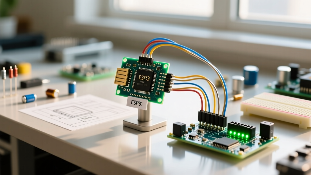
- ESP32-S3 / FreeRTOS: On the ESP32, standard Arduino delays can be preempted by the FreeRTOS scheduler, causing massive jitter. For precise peripheral timing, bypass the Arduino wrapper and use the ESP-IDF ROM function:
esp_rom_delay_us(us);. This executes entirely in ROM and is immune to RTOS context switching. - Teensy 4.1 (600MHz ARM Cortex-M7): The Teensy ecosystem provides
delayNanoseconds(ns). Because the MCU runs at 600MHz, one clock cycle is 1.66ns. This allows for staggering precision without assembly hacks. As detailed in the PJRC Teensy timing documentation, leveraging hardware cycle counters viaARM_DWT_CYCCNTis the gold standard for sub-microsecond profiling. - Hardware Timers (All Architectures): For generating continuous square waves or PWM signals, never use
delayMicroseconds()in a loop. Instead, configure a hardware timer (e.g., Timer1 on AVR, LEDC peripheral on ESP32) to toggle the pin automatically in the background, freeing the CPU for other tasks.
Frequently Asked Questions
Does delayMicroseconds consume power?
Yes. Because it is a 'busy-wait' loop, the CPU remains fully active, executing dummy instructions. It does not put the microcontroller into sleep or idle mode. For battery-powered IoT nodes, you should use hardware sleep timers instead.
Can I use floating-point numbers with this function?
No. The function strictly accepts unsigned integers. If your math results in 10.5, it will be truncated to 10. Perform your calculations using integer math (e.g., multiply by 10, calculate, then divide) to preserve precision before passing the final integer to the function.
Why is my NeoPixel library failing on an ATTiny85?
The ATTiny85 often runs at 8MHz or 16MHz via internal oscillator, which has a factory tolerance of ±10%. This clock drift alters the actual duration of delayMicroseconds(), pushing the timing outside the strict ±150ns tolerance required by WS2812B LEDs. You must use a crystal oscillator or calibrate the internal oscillator's OSCCAL register.