
The GPIO Limitation: Why You Need a Motor Driver
When learning how to control motors with Arduino, the most common beginner mistake is attempting to power a DC motor directly from the microcontroller's GPIO pins. Whether you are using a classic Arduino Uno R3 (ATmega328P) or the modern Arduino Uno R4 Minima (Renesas RA4M1), the I/O pins are strictly limited. The R3 can source a maximum of 40mA per pin, while the R4 is limited to just 8mA. A standard 3V to 6V hobby DC motor typically draws between 500mA and 2A under load. Connecting a motor directly to an Arduino pin will instantly fry the microcontroller's internal logic gates due to overcurrent and back-electromotive force (back-EMF) voltage spikes.
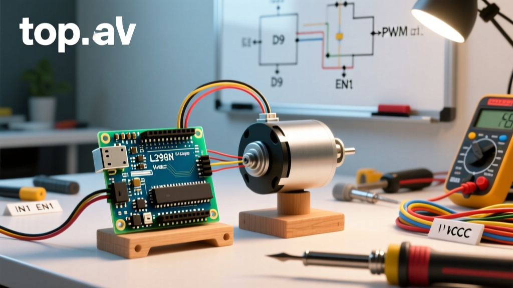
To safely interface high-current inductive loads with low-current logic, you must use an H-Bridge motor driver. This guide provides a deep-dive configuration walkthrough for the two most ubiquitous drivers in the maker ecosystem: the legacy BJT-based L298N and the modern MOSFET-based TB6612FNG.
Hardware Selection: L298N vs. TB6612FNG (2026 Comparison)
While the L298N has been the default educational motor driver for over a decade, the TB6612FNG has largely superseded it in professional and advanced hobbyist projects due to vastly superior efficiency. Below is a technical comparison to help you choose the right board for your configuration.
| Specification | L298N (Generic Module) | TB6612FNG (SparkFun/Pololu) |
|---|---|---|
| Transistor Technology | Bipolar Junction Transistor (BJT) | MOSFET (Metal-Oxide-Semiconductor) |
| Continuous Current per Channel | 2.0A (Requires massive heatsink) | 1.2A (3.2A Peak for 10 seconds) |
| Voltage Drop (Vce_sat / Rds_on) | ~2.0V to 2.5V (High heat loss) | ~0.5V at 1A (Highly efficient) |
| Motor Supply Voltage (VM) | 5V to 35V | 2.5V to 13.5V (15V Absolute Max) |
| Logic Voltage (VCC) | 5V (Onboard 7805 regulator) | 2.7V to 5.5V |
| PWM Frequency Limit | ~25 kHz (Struggles above 5 kHz) | 100 kHz max |
| Typical 2026 Market Price | $3.00 - $5.00 | $6.00 - $9.00 |
Configuring the L298N: Wiring and Power Edge Cases
The L298N module is physically large and features a built-in 7805 linear voltage regulator. While this seems convenient for powering the Arduino, it introduces severe thermal edge cases that you must configure correctly.
The 5V Jumper Trap
On the L298N board, there is a jumper cap located near the 5V and GND output terminals. This jumper enables the onboard 7805 regulator, which steps down the motor supply voltage (12V input) to 5V to power the logic chip and the Arduino.
- If your motor supply is 12V or less: Leave the jumper ON. You can wire the module's 5V output to the Arduino's 5V pin (if using a barebones setup) or Vin pin. However, be aware that the 7805 will dissipate (12V - 5V) × Current as heat. At just 300mA of logic draw, it generates 2.1W of heat, which will trigger thermal shutdown without active cooling.
- If your motor supply exceeds 12V (e.g., 24V for NEMA steppers): You MUST remove the jumper. The 7805 regulator has a maximum input voltage of around 35V, but the thermal dissipation at 24V will instantly destroy the regulator. Instead, power the module's logic by feeding 5V from the Arduino into the module's 5V terminal.
Wiring Configuration
For a standard dual-motor setup, connect your Arduino PWM-capable pins (e.g., D5 and D6) to ENA and ENB. Connect standard digital pins (e.g., D4, D7, D8, D9) to IN1, IN2, IN3, and IN4. Crucially, the GND of the L298N, the Arduino, and the external battery pack must all share a common ground reference; otherwise, the logic signals will float and cause erratic motor behavior.
Configuring the TB6612FNG: The Modern MOSFET Approach
The TB6612FNG is vastly superior for battery-operated robots and precision control. Because it uses MOSFETs, the voltage drop is minimal, meaning a 6V battery pack will actually deliver ~5.5V to your motors, compared to the ~3.5V you would get through an L298N.
The Standby (STBY) Pin Requirement
Unlike the L298N, the TB6612FNG features a dedicated STBY (Standby) pin. According to the Texas Instruments TB6612FNG datasheet, if this pin is left floating or pulled LOW, the internal logic is completely disabled to save power. Beginners frequently wire the motor driver, upload the code, and wonder why the motors refuse to spin. You must wire the STBY pin directly to the Arduino's 5V (VCC) output, or to a digital pin that you explicitly write HIGH in your setup() function.
Separating VM and VCC
The TB6612FNG requires two separate power inputs:
- VM (Motor Supply): Connect to your battery pack (2.5V to 13.5V).
- VCC (Logic Supply): Connect to the Arduino's 5V or 3.3V output (depending on your board's logic level).
This separation completely isolates the noisy motor power from the sensitive microcontroller logic, drastically reducing the chance of brownout resets.
Software Configuration: Deadbands and PWM Mapping
When you use the Arduino analogWrite reference to send a PWM signal, a value of 1 does not equate to a slowly turning motor. DC motors suffer from static friction and cogging torque. If you send a PWM value of 30 (out of 255), the motor will likely just whine and vibrate without rotating. This is known as the "deadband.Both drivers require deadband compensation in software to achieve smooth low-speed control.
Expert Tip: Never map your joystick or PID output directly from 0-255 to the PWM pin. Instead, map the active range from your minimum deadband threshold (usually 50-70) to 255.
Here is the logical framework for implementing deadband compensation in C++:
int deadband_min = 60; // Motor starts spinning reliably at PWM 60
int input_speed = analogRead(A0); // 0 to 1023 from a potentiometer
int mapped_speed = map(input_speed, 0, 1023, -255, 255);

int pwm_output;
if (abs(mapped_speed) < 50) {
  pwm_output = 0; // Inside the deadzone, stop the motor
} else if (mapped_speed > 0) {
  pwm_output = map(mapped_speed, 50, 255, deadband_min, 255);
} else {
  pwm_output = -map(mapped_speed, -255, -50, deadband_min, 255);
}
This configuration ensures that the moment the motor is commanded to move, it receives enough initial voltage to break static friction, resulting in smooth, proportional control.
Power Decoupling and Flyback Protection
Inductive loads like DC motors generate massive voltage spikes when power is removed (back-EMF). While both the L298N and TB6612FNG feature built-in flyback diodes to protect the H-Bridge transistors, relying solely on them is poor engineering practice for long-term reliability. To properly configure your power delivery network (PDN), implement the following decoupling strategy:
- Local Motor Decoupling: Solder a 100nF (0.1µF) ceramic capacitor directly across the two terminals of the DC motor. This suppresses high-frequency EMI generated by the physical carbon brushes arcing against the commutator.
- Bus Decoupling: Place a large electrolytic capacitor (e.g., 470µF to 1000µF, rated for at least 25V) across the main VM and GND rails on your breadboard or perfboard. This acts as a local energy reservoir to handle the massive inrush current when the motor starts, preventing the voltage rail from sagging and resetting the Arduino.
- Twisted Pair Wiring: Run your motor wires as a twisted pair to minimize the loop area, which drastically reduces radiated electromagnetic interference that can corrupt I2C or SPI sensor data on your Arduino.
Troubleshooting Common Failure Modes
Even with correct wiring, motor control circuits often exhibit edge-case failures. Use this diagnostic matrix to resolve common issues based on the Arduino official electronics motors guide and field engineering data.
| Symptom | Probable Cause | Configuration Fix |
|---|---|---|
| Arduino resets when motor accelerates | Brownout due to voltage sag on the 5V rail. | Isolate motor power from Arduino 5V. Add a 1000µF bulk capacitor to the motor VM rail. |
| Motor moves in one direction but not the other | Blown H-Bridge channel or floating logic pin. | Test IN1/IN2 with a multimeter. Ensure no internal pull-up resistors are conflicting with driver logic. |
| L298N gets too hot to touch within 10 seconds | 7805 thermal overload or excessive BJT Vce drop. | Switch to a TB6612FNG or add a dedicated buck converter (e.g., LM2596) for logic power. |
| High-pitched whining noise from motor | PWM frequency is within human hearing range (490Hz). | Reconfigure Arduino timer registers to output PWM at 20kHz+ (ultrasonic), supported natively by TB6612FNG. |
Final Configuration Recommendations
If you are building a simple, low-budget educational demonstrator where efficiency is irrelevant, the L298N remains a viable, robust option that can tolerate accidental wiring shorts better than MOSFET drivers. However, for any mobile robotics, battery-powered rovers, or precision CNC applications in 2026, the TB6612FNG is the mandatory standard. Its low Rds(on) resistance preserves battery life, its 100kHz PWM support allows for silent motor operation, and its compact footprint frees up valuable chassis space. Always prioritize proper grounding topology and software deadband mapping to achieve professional-grade motion control.