
The Evolution of DIY Electromagnetic Sensing
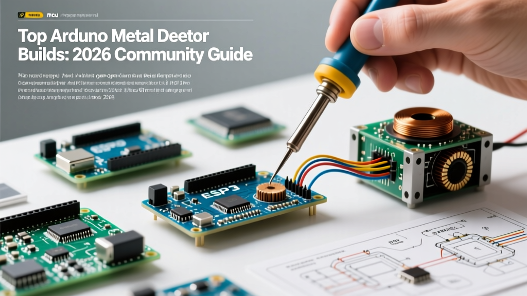
Building an Arduino metal detector has transitioned from a niche weekend experiment to a highly refined sub-genre of the maker community. As of 2026, open-source hardware repositories and community forums have yielded designs that rival entry-level commercial units in depth and discrimination. By leveraging modern microcontrollers like the Arduino Uno R4 Minima and the Nano 33 IoT, makers are implementing digital signal processing (DSP) techniques that were previously restricted to expensive, proprietary ASICs.
This community resource roundup dissects the top three open-source architectures currently dominating the maker space. We will cover the analog front-end (AFE) requirements, specific coil winding parameters, and the edge cases that separate a functioning prototype from a reliable field instrument.
2026 Community Project Roundup: Top 3 Architectures
1. The Classic BFO (Beat Frequency Oscillator)
The Beat Frequency Oscillator remains the most accessible entry point for beginners. The community consensus for 2026 favors a dual-oscillator design where a reference oscillator (typically fixed at 100 kHz using a CMOS 74HC04 hex inverter) is mixed with a variable search coil oscillator. The Arduino measures the resulting beat frequency using hardware interrupts.
- Microcontroller: Arduino Nano (Classic or Every)
- Core Logic: Uses
attachInterrupt()to count zero-crossings over a 100ms window. - Pros: Simple AFE, requires only a few passive components and a single transistor (e.g., 2N3904 or BF494).
- Cons: Poor target discrimination; cannot easily distinguish between ferrous and non-ferrous metals.
2. Induction Balance (IB) with Arduino Uno R4 Minima
For makers seeking target discrimination, the Induction Balance architecture is the gold standard. This design uses coplanar transmit (TX) and receive (RX) coils. The TX coil is driven by a continuous sine or square wave, while the RX coil is positioned to null out the primary magnetic field. When metal enters the field, the balance is disrupted, inducing a phase-shifted voltage in the RX coil.
The community has heavily adopted the Arduino Uno R4 Minima for this build due to its 14-bit ADC, which provides the granular resolution required to detect microvolt-level phase shifts without an external ADC. The analog signal is typically amplified using a low-noise TL072 op-amp before hitting the microcontroller.
3. Pulse Induction (PI) for High-Mineralization Soils
Pulse Induction ignores ground mineralization by sending high-current, microsecond pulses into the search coil and measuring the decay time of the reflected eddy currents. While historically difficult to implement on standard 8-bit AVRs due to timing constraints, the community has successfully ported PI routines to the Arduino Portenta H7 and Nano 33 IoT, utilizing their 32-bit ARM Cortex-M cores to capture nanosecond decay curves via direct memory access (DMA).
Component Sourcing & Cost Breakdown
Below is a comparative BOM (Bill of Materials) based on average 2026 community sourcing from vendors like Mouser, DigiKey, and Adafruit. Prices reflect single-unit hobbyist tiers.
| Architecture | Primary MCU | Key AFE Components | Est. BOM Cost | Complexity |
|---|---|---|---|---|
| BFO | Nano Every ($12) | 74HC04, 2N3904, 10nF NP0 Caps | $28 - $35 | Low |
| Induction Balance | Uno R4 Minima ($22) | TL072 Op-Amp, 10uH RF Chokes | $55 - $70 | High |
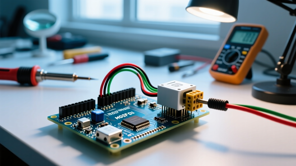
| Pulse Induction | Nano 33 IoT ($24) | IRF740 MOSFET, Snubber Network | $65 - $85 | Expert |
Deep Dive: Winding the Search Coil
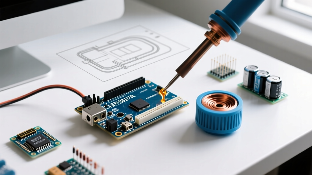
The search coil is the heart of any Arduino metal detector. A poorly wound coil will destroy the Q-factor (quality factor) of your resonant circuit, rendering even the most optimized Arduino sketch useless. The community standard for a general-purpose 20cm (8-inch) search coil follows this exact specification:
- Wire Selection: Use 24 AWG enameled copper magnet wire. Thicker wire lowers DC resistance, improving the Q-factor.
- Winding the Former: Wrap exactly 55 to 60 turns around a non-conductive, non-magnetic former (HDPE or wood). Maintain a tight, uniform winding geometry to minimize parasitic capacitance.
- Inductance Target: Aim for 250 µH to 300 µH. Verify with an LCR meter before proceeding.
- Insulation: Wrap the entire coil in 3 layers of PTFE (Teflon) tape. Do not use standard vinyl electrical tape, as its adhesive can degrade and introduce moisture-induced capacitance drift.
- The Faraday Shield (Crucial): Wrap the coil in aluminum foil to block electrostatic interference from grass and soil moisture. However, you must leave a 5mm gap at the top of the shield. If the foil forms a complete loop, it acts as a shorted secondary turn, completely killing the magnetic field.
Community Maker Tip: 'Always secure your coil leads with a twisted pair configuration all the way to the PCB. Untwisted leads act as an antenna, picking up 50/60Hz mains hum and ruining your signal-to-noise ratio.' — OpenMetalDetect Forum, 2025
Digital Signal Processing & Code Implementation
For BFO and IB detectors, relying on delay() or simple polling loops will result in missed beats and jittery audio feedback. The community standard approach utilizes hardware interrupts to ensure precise timing, independent of the main loop's execution time. According to the official Arduino attachInterrupt() documentation, mapping the oscillator output to a hardware interrupt pin (like Pin 2 or 3 on an Uno) allows the MCU to count frequency shifts with microsecond accuracy.
For audio feedback, makers are moving away from the blocking tone() function. Instead, they utilize Timer1 PWM to generate a synthesized sine wave, modulating the frequency in real-time based on the target's phase angle. This allows for distinct audio tones for ferrous (low pitch) versus non-ferrous (high pitch) targets.
Edge Cases & Troubleshooting EMI
Even with a perfect schematic, environmental and hardware edge cases can cripple an Arduino-based detector. Here is how the community solves the most persistent issues:
1. USB Cable EMI During Tethered Testing
When debugging your sketch while the Arduino is connected to a laptop via USB, the unshielded USB cable often acts as a massive antenna, injecting switching noise from the PC's power supply into the AFE. Solution: Always perform final tuning and threshold calibration on battery power. If you must tether, use a double-shielded USB cable with a ferrite choke clamped near the Arduino's USB port. The FCC's guidelines on RFI highlight how unshielded data cables can easily radiate and receive harmonic interference in the 100kHz to 5MHz bands, which overlaps directly with BFO operating frequencies.
2. Ground Mineralization False Positives
Soils rich in iron oxide or salt will trigger false positives. In an IB detector, this is solved via 'Ground Balancing.' The community implements this by adding a digitally controlled potentiometer (like the MCP4131) to the AFE. The Arduino sweeps the potentiometer on startup, sampling the RX coil until the baseline phase shift reads zero, effectively 'tuning out' the soil.
3. Thermal Drift in Capacitors
Using standard Y5V or X7R ceramic capacitors in the LC tank circuit is a common rookie mistake. These dielectrics exhibit massive capacitance shifts with temperature changes, causing the detector to constantly drift out of tune. Solution: Only use NP0/C0G dielectric capacitors for all resonant and timing circuits. They offer near-zero thermal drift, ensuring your beat frequency remains stable from a cold morning to a hot afternoon.
Frequently Asked Questions (FAQ)
Can I use a standard Arduino Uno R3 for an Induction Balance detector?
While possible, the Uno R3's 10-bit ADC lacks the dynamic range required to resolve the microvolt signals of an IB coil without heavy external amplification. Upgrading to the Uno R4 Minima (14-bit ADC) or using an external 24-bit ADC (like the ADS1256) is highly recommended for stable discrimination.
How deep can a DIY Arduino metal detector realistically detect?
A well-tuned 20cm BFO or IB coil built to the specifications above can reliably detect a US Quarter-sized coin at depths of 15cm to 22cm (6 to 9 inches) in dry soil. Claims exceeding 30cm for single-coin detection in DIY hobbyist builds usually involve heavily exaggerated testing conditions or ignore the inverse-cube law of electromagnetic induction, which dictates that signal strength drops off exponentially with distance.
Do I need to waterproof the Arduino enclosure?
Yes. Even if you don't submerge the control box, morning dew and high humidity will cause condensation inside the enclosure, leading to parasitic leakage currents across the PCB traces. Use a silicone conformal coating on the analog sections of your custom PCB, and seal the enclosure with a neoprene gasket.