
Essential Hardware for Arduino SD Card Integration
Understanding how to connect an SD card module to Arduino is a foundational skill for any embedded systems engineer or maker building offline data loggers, GPS trackers, or environmental monitors. As of 2026, while cloud-connected ESP32 boards dominate IoT, local MicroSD storage remains critical for high-frequency sampling, remote deployments without cellular coverage, and fail-safe black-box logging.
Before wiring anything, you must select the correct hardware. The market offers two primary types of MicroSD breakouts:
- Raw 3.3V Breakouts (e.g., Adafruit 254): These expose the SD card pins directly. They require a strict 3.3V power supply and 3.3V logic levels. Connecting these directly to a 5V Arduino Uno will permanently damage the card's internal controller.
- 5V-Tolerant Adapter Modules (e.g., Catalex v1.0 or LC Studio): These are the most common and cost-effective ($2 to $4). They feature an onboard AMS1117-3.3 LDO voltage regulator to step down 5V to 3.3V, and a logic level shifting IC (like the 74LVC125A) or resistor divider network to safely translate the 5V SPI signals from the Arduino.
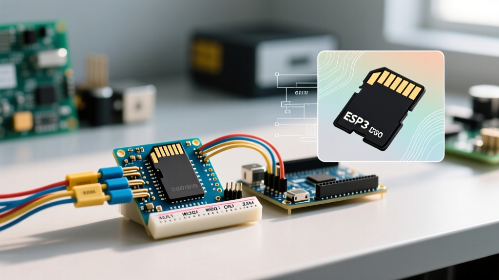
For this tutorial, we will use the ubiquitous 5V-tolerant MicroSD adapter module paired with an Arduino Uno R4 Minima (or classic Uno R3) and a 32GB Class 10 MicroSDHC card (such as the SanDisk Ultra, typically priced around $8).
Expert Warning: Do not use 64GB or larger SDXC cards. SDXC cards are pre-formatted in exFAT, which the standard Arduino SD library does not support natively. Stick to SDHC cards (4GB to 32GB) formatted as FAT32.
SPI Protocol and Pinout Matrix
MicroSD cards communicate using the Serial Peripheral Interface (SPI) bus. SPI is a synchronous serial communication interface used for short-distance, primarily in embedded systems. The SD module requires four shared SPI lines plus power and ground.
Below is the definitive wiring matrix for connecting the SD module to popular 5V Arduino boards:
| SD Module Pin | Arduino Uno R3 / R4 | Arduino Mega 2560 | Arduino Nano (Classic) | Function Description |
|---|---|---|---|---|
| GND | GND | GND | GND | Common Ground Reference |
| VCC | 5V | 5V | 5V | Power Input (Module LDO steps to 3.3V) |
| MISO | Pin 12 | Pin 50 | Pin 12 | Master In, Slave Out (Data to Arduino) |
| MOSI | Pin 11 | Pin 51 | Pin 11 | Master Out, Slave In (Data to SD) |
| SCK | Pin 13 | Pin 52 | Pin 13 | Serial Clock (Timing Signal) |
| CS | Pin 10 (or 4) | Pin 53 (or 4) | Pin 10 (or 4) | Chip Select (Slave Select) |
Note: While the hardware SPI pins (MISO, MOSI, SCK) are fixed to the ATmega microcontroller's internal hardware routing, the CS (Chip Select) pin can be any digital I/O pin. However, Pin 10 on the Uno/Nano and Pin 53 on the Mega must be set as OUTPUT in your code, even if you use a different pin for CS, to ensure the ATmega remains in SPI Master mode.
The #1 Point of Failure: SD Card Formatting
Over 80% of initialization failures when learning how to connect an SD card module to Arduino stem from improper file system formatting. Windows and macOS native formatting tools often default to exFAT for larger cards or use an incompatible Master Boot Record (MBR) structure.
To guarantee compatibility with the Arduino SD.h library, follow these exact formatting parameters:
- Download the official SD Memory Card Formatter from the SD Association.
- Select your MicroSD card and choose Overwrite Format (not Quick Format) to wipe any hidden partition tables.
- Ensure the file system is set to FAT32.
- Set the Allocation Unit Size (Cluster Size) to 32KB. This specific cluster size optimizes the SPI write buffer and prevents excessive wear leveling overhead on the flash memory.
Step-by-Step Wiring and Decoupling
Follow this sequence to wire the circuit safely:
- Power Down: Disconnect the Arduino from USB or external power.
- SPI Routing: Connect MISO, MOSI, and SCK to their respective hardware pins as per the matrix above.
- Chip Select: Connect the CS pin to Digital Pin 10.
- Power & Decoupling: Connect VCC to 5V and GND to GND. Critical Engineering Step: Solder or plug a 100µF electrolytic capacitor directly across the VCC and GND pins on the SD module. MicroSD cards can draw current spikes of 150mA to 200mA during write bursts. Without local decoupling, this causes voltage brownouts that reset the Arduino or corrupt the FAT table mid-write.
- Insert Card: Slide the formatted MicroSD card into the module until it clicks.
Robust C++ Implementation for Data Logging
The official Arduino SD Library Documentation provides basic examples, but production-grade data logging requires strict file handling to prevent corruption. The code below initializes the card, creates a CSV file, appends sensor data, and crucially, forces a buffer flush to the physical NAND flash.
#include <SPI.h>
#include <SD.h>

const int chipSelect = 10;
File dataFile;

void setup() {
  Serial.begin(115200);
  while (!Serial) { ; } // Wait for serial port (Uno R4 / Leonardo)

  // Pin 10 must be OUTPUT for Uno/Nano SPI Master mode
  pinMode(10, OUTPUT);
  pinMode(LED_BUILTIN, OUTPUT);

  Serial.print("Initializing SD card...");

  // Initialize at a slower SPI speed to ensure reliable startup
  if (!SD.begin(chipSelect, SPI_HALF_SPEED)) {
    Serial.println("Card failed, or not present");
    while (1); // Halt execution
  }
  Serial.println("Wiring and initialization successful.");

  // Open file in append mode. FILE_WRITE appends in the standard SD.h lib
  dataFile = SD.open("datalog.csv", FILE_WRITE);
  if (dataFile) {
    // Write CSV header if file is new (size == 0)
    if (dataFile.size() == 0) {
      dataFile.println("Timestamp_ms,Analog_A0,Temp_C");
    }
    dataFile.close();
  } else {
    Serial.println("Error opening datalog.csv");
  }
}

void loop() {
  unsigned long currentTime = millis();
  int sensorValue = analogRead(A0);
  // Mock temperature conversion for demonstration
  float temperature = (sensorValue * 5.0 / 1024.0) * 100.0;

  dataFile = SD.open("datalog.csv", FILE_WRITE);
  if (dataFile) {
    dataFile.print(currentTime);
    dataFile.print(",");
    dataFile.print(sensorValue);
    dataFile.print(",");
    dataFile.println(temperature);

    // CRITICAL: Flush forces the RAM buffer to write to the physical SD card
    dataFile.flush();
    dataFile.close();

    // Visual heartbeat indicator
    digitalWrite(LED_BUILTIN, HIGH);
    delay(50);
    digitalWrite(LED_BUILTIN, LOW);
  }

  // Log every 2 seconds
  delay(1950);
}
Advanced Troubleshooting & Edge Cases
Even with perfect wiring, SPI communication can be temperamental. Use this diagnostic matrix to resolve common failure modes:
| Error Symptom | Root Cause Analysis | Engineering Fix |
|---|---|---|
SD.begin() returns false |
SPI clock speed is too high for the module's logic shifters or the card's controller. | Pass SPI_HALF_SPEED or SPI_QUARTER_SPEED as the second argument in SD.begin(). |
| File creates but is 0 bytes | Missing flush() or close() command, or Arduino reset before buffer writes. |
Always call dataFile.flush() before dataFile.close() in your logging loop. |
| Random Arduino Resets during write | Current spike brownout on the 5V rail during NAND flash programming. | Install a 100µF - 220µF low-ESR capacitor across the SD module VCC/GND pins. |
| Card works on PC, fails on Arduino | Partition table is GPT instead of MBR, or cluster size is unsupported. | Reformat using the official SD Association Formatter tool with MBR and 32KB clusters. |
| MISO/MOSI cross-talk | Long jumper wires acting as antennas, picking up EMI from the SCK line. | Keep SPI wires under 10cm. Twist MISO/MOSI wires around the GND wire for shielding. |
A Note on the CS (Chip Select) Pin
If you are integrating the SD card module alongside other SPI devices (like an NRF24L01 radio or an SPI OLED display), remember that every SPI slave device must have its own unique CS pin. The Arduino's hardware SPI bus (MISO, MOSI, SCK) is shared, but pulling a device's CS pin LOW is what activates it. Ensure all unused SPI slave CS pins are pulled HIGH via digitalWrite(csPin, HIGH) in your setup() function to prevent them from interfering with the SD card's SPI bus arbitration.
By adhering to strict formatting protocols, implementing local power decoupling, and utilizing robust file-handling code, your Arduino SD card integration will yield enterprise-grade reliability for long-term data logging deployments.