
The Hidden Bottleneck in Arduino Sensor Projects
Most makers treat Arduino sensors as plug-and-play components, relying on default library settings that sacrifice accuracy for convenience. Whether you are building a greenhouse climate monitor with a Bosch BME280 or a balancing robot using an InvenSense MPU-6050, out-of-the-box configurations rarely account for real-world electrical noise, bus capacitance, or thermal drift. As the maker ecosystem evolves in 2026—with boards like the Uno R4 Minima introducing 12-bit ADCs and hardware FPU for Edge ML—understanding the low-level configuration of your sensors is no longer optional; it is the difference between a toy and a professional-grade instrument.
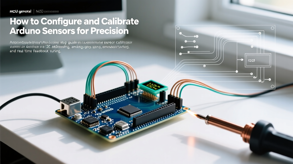
This configuration guide bypasses basic wiring tutorials and dives deep into the electrical and mathematical tuning required to extract precise, noise-free data from your Arduino sensors.
I2C Bus Configuration: Pull-Ups, Capacitance, and Addresses
The I2C protocol is the backbone of modern digital Arduino sensors. However, it is highly susceptible to parasitic capacitance, which degrades signal integrity and causes silent data corruption or bus lockups.
Managing Bus Capacitance and Pull-Up Resistors
According to the NXP I2C-bus specification (UM10204), the maximum allowable bus capacitance is 400pF. Every wire, breadboard contact, and sensor module adds to this total. If you are running a 3-meter CAT5 cable to a remote temperature probe, your capacitance will easily exceed this limit, rounding off the sharp edges of your I2C clock signals.
- Standard Mode (100kHz): Use 4.7kΩ pull-up resistors for short runs (<30cm) with 1-2 sensors.
- Fast Mode (400kHz): Drop to 2.2kΩ pull-ups to charge the bus capacitance faster.
- Long-Run / High Capacitance: Use an active I2C terminator like the LTC4311, or drop the bus speed to 50kHz using
Wire.setClock(50000);in your setup routine.
Expert Tip: Many cheap breakout boards include onboard 10kΩ pull-up resistors. If you daisy-chain three of these sensors, the parallel resistance drops to ~3.3kΩ, which might seem fine, but it creates uneven voltage thresholds. Always check your schematic and physically des onboard SMD resistors if you are using a centralized, properly sized pull-up array on your custom PCB.
Resolving I2C Address Collisions
A common configuration hurdle is address collision. Below is a matrix of popular Arduino sensors and their default hex addresses.
| Sensor Model | Function | Default I2C Address | Alternative Address |
|---|---|---|---|
| Bosch BME280 | Temp/Hum/Press | 0x76 | 0x77 (via SDO pin) |
| MPU-6050 | 6-Axis IMU | 0x68 | 0x69 (via AD0 pin) |
| ADS1115 | 16-bit ADC | 0x48 | 0x49, 0x4A, 0x4B |
| VL53L0X | Time-of-Flight | 0x29 | Software configurable |
If your project requires multiple identical sensors (e.g., four VL53L0X LiDAR sensors for robot navigation), you must configure them dynamically. Alternatively, use an I2C multiplexer like the NXP TCA9548A, which allows you to route the I2C bus to 8 separate channels, effectively bypassing address limitations entirely.
Analog Sensor Configuration and ADC Tuning
While digital sensors dominate, analog Arduino sensors (like photoresistors, MQ gas sensors, and basic thermistors) require meticulous Analog-to-Digital Converter (ADC) configuration.
Selecting the Correct Voltage Reference
By default, the analogRead() function uses the board's VCC (usually 5V or 3.3V) as the reference. This is a critical mistake for precision work, as USB power from a PC can fluctuate between 4.7V and 5.2V, directly injecting noise into your sensor readings.
Configure your ADC reference explicitly in the setup() block:
analogReference(INTERNAL); // Uses internal 1.1V or 2.5V reference
// OR
analogReference(EXTERNAL); // Uses voltage applied to the AREF pin
For high-precision thermistor or load cell configurations, feed a dedicated, low-noise voltage reference IC (like the LM4040 2.048V) into the AREF pin and set the reference to EXTERNAL. This guarantees that 1 ADC step always represents an exact, unchanging voltage increment.
Hardware vs. Software Oversampling
To reduce Gaussian noise in analog Arduino sensors, you must oversample. Here is a comparison of how to configure your oversampling strategy based on your microcontroller's capabilities.
| Method | Implementation | Pros | Cons |
|---|---|---|---|
| Hardware Oversampling | Configuring ADC registers (e.g., SAMD21 or Uno R4) | Zero CPU overhead; highly accurate. | Requires deep register knowledge; board-specific. |
| Software Averaging (SMA) | Looping analogRead() 16-64 times and dividing. |
Easy to implement; works on any board. | Blocks CPU execution; poor response to sudden spikes. |
| Exponential Moving Average (EMA) | Applying an alpha-weighted mathematical filter. | Low memory footprint; smooths data continuously. | Introduces slight phase lag in fast-moving systems. |
For most 2026 maker projects utilizing an Uno R3 or Nano, the EMA is the superior software choice. It requires only one floating-point variable and reacts gracefully to transient noise spikes:
float alpha = 0.1; // Smoothing factor (0.01 to 0.5)
float smoothedValue = 0;

void loop() {
  int rawRead = analogRead(A0);
  smoothedValue = (alpha * rawRead) + ((1.0 - alpha) * smoothedValue);
}
Configuring Digital Interrupts for Low-Power Sensor Nodes
When deploying battery-powered Arduino sensors in remote locations (e.g., LoRaWAN soil moisture nodes), polling sensors in the loop() will drain your battery in days. You must configure hardware interrupts to wake the MCU only when a specific physical threshold is crossed.
Step-by-Step Interrupt Configuration
- Enable Sensor-Side Interrupts: Access the sensor's configuration registers via I2C. For example, on the ADS1115, write to the Lo_thresh and Hi_thresh registers and enable the ALERT pin.
- Route to MCU INT Pin: Connect the sensor's ALERT/INT pin to an interrupt-capable pin on the Arduino (Pins 2 or 3 on the Uno).
- Configure the ISR: Use
attachInterrupt(digitalPinToInterrupt(pin), wakeUp, FALLING);. - Sleep the MCU: Utilize the Arduino Wire library and standard AVR sleep modes (
set_sleep_mode(SLEEP_MODE_PWR_DOWN);) to drop current consumption to micro-amps until the sensor triggers the pin.
Edge Case Warning: Mechanical switches suffer from contact bounce, requiring software debouncing. However, digital sensor INT pins are solid-state and clean. Do not use software debounce delays in your Interrupt Service Routine (ISR) for digital sensors, as this will cause missed events and bus lockups. Keep your ISR under 5 microseconds—simply set a volatile boolean flag and handle the I2C read in the main loop.
Real-World Calibration Workflows
Configuration is incomplete without calibration. Here is how to calibrate two of the most common Arduino sensor types.
1. Two-Point Temperature Calibration (Thermistors)
Do not rely on the nominal 10kΩ resistance listed on the datasheet. Manufacturing tolerances can introduce a ±1°C error right out of the box.
- Step 1: Submerge the sensor in an ice-water bath (0.0°C). Record the raw ADC value.
- Step 2: Submerge the sensor in boiling water (adjust for your local altitude and barometric pressure). Record the raw ADC value.
- Step 3: Calculate the actual Steinhart-Hart coefficients (A, B, and C) using an online Steinhart-Hart calculator, replacing the generic coefficients provided in standard Arduino libraries.
2. IMU Gyroscope Drift Calibration
MEMS gyroscopes (like the MPU-6050) suffer from zero-rate drift. If you do not calibrate the offsets, your robot will slowly turn in circles over time.
- Place the sensor on a perfectly level, vibration-free surface.
- Read the raw X, Y, and Z gyro registers 2,000 times in a tight loop.
- Average these readings to find the zero-error offset.
- Write these offsets directly to the sensor's internal offset registers (e.g.,
0x13to0x18on the MPU-6050) so the hardware corrects the data before it even hits the I2C bus.
Frequently Asked Questions
Why are my I2C Arduino sensors returning -1 or NaN?
A return value of -1 usually indicates a failed I2C handshake (NACK). This is almost always caused by a wiring error, an incorrect I2C address, or missing pull-up resistors on the SDA/SCL lines. NaN (Not a Number) in floating-point math usually means the sensor returned raw data of all 1s (0xFF), which happens when the bus is pulled high but no device is actually driving the data line.
Can I mix 5V and 3.3V sensors on the same I2C bus?
Never connect a 5V I2C master directly to a 3.3V sensor without logic level shifting. The SDA/SCL lines will push 5V into the sensor's logic pins, potentially degrading or destroying the silicon over time. Use a bidirectional logic level converter (like the BSS138 MOSFET-based shifters) to safely bridge the two voltage domains.
How do I configure multiple SPI sensors?
Unlike I2C, SPI does not use addresses. Instead, every SPI sensor requires its own dedicated Chip Select (CS) pin. To configure multiple SPI Arduino sensors, define a unique CS pin for each device, set them all to OUTPUT and HIGH in your setup, and pull the specific CS pin LOW only when actively communicating with that individual sensor.