
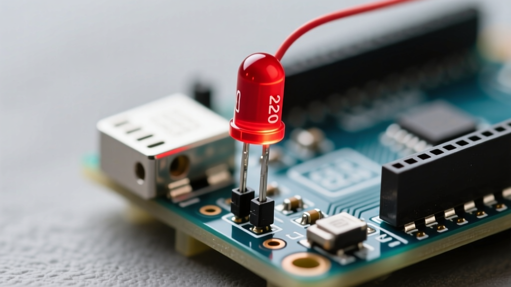
To choose the correct resistor for a standard 5-Volt Arduino board and a typical red Light Emitting Diode, use a 220-ohm resistor. This specific value limits the electrical current to a safe 15 milliamperes, protecting both the microcontroller output pin and the diode from thermal damage. If you are using a 3.3-Volt board or different colored diodes, you must recalculate the resistance using Ohm's Law. This guide is engineered for beginner to intermediate hardware makers, robotics students, and DIY electronics hobbyists building microcontroller circuits.
- Use a 220-ohm resistor for standard red LEDs on 5-Volt Arduino boards.
- Always calculate resistance using the specific Forward Voltage of your LED color.
- Never exceed 20 milliamperes per digital I/O pin to avoid permanent microcontroller damage.
The Core Formula: Calculating Your Resistor
Selecting the proper component requires understanding the electrical characteristics of both the microcontroller and the light source. Relying on guesswork often leads to dim illumination or destroyed silicon.
Understanding Ohm's Law for Light Emitting Diodes
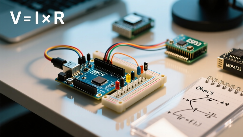
A Current Limiting Resistor is a passive two-terminal electrical component placed in series with a load to restrict electrical flow. In microcontroller circuits, it prevents excessive current from destroying sensitive semiconductor junctions. The resistance value is calculated using the supply voltage, forward voltage, and desired operating current.
Forward Voltage is the specific voltage drop across a Light Emitting Diode when it is conducting electrical current. Measured in Volts, this value varies by the semiconductor material and emitted color. Red diodes typically require 2.0 Volts, while blue and white variants demand approximately 3.3 Volts to illuminate properly.
The calculation follows this formula: Resistance = (Supply Voltage - Forward Voltage) / Target Current.
Standard Arduino Pin Specifications
According to the Arduino Uno Rev3 Documentation, the absolute maximum current per I/O pin is 40 milliamperes. However, operating at the absolute maximum degrades the microcontroller over time.
The recommended continuous operating current is 20 milliamperes. For long-term reliability and to account for component tolerances, targeting 15 milliamperes (0.015 Amperes) is the industry standard for indicator lights.
Quick Reference: Resistor Sizing Table
Use this decision framework to select the correct component for the most common Arduino boards and diode colors. These values assume a target current of 15 milliamperes.
| Board Type | Supply Voltage | LED Color | Forward Voltage | Calculated Resistance | Standard E12 Value |
|---|---|---|---|---|---|
| Arduino Uno R4 / Rev3 | 5.0 Volts | Red | 2.0 Volts | 200 ohms | 220 ohms |
| Arduino Uno R4 / Rev3 | 5.0 Volts | Green | 2.2 Volts | 186 ohms | 180 ohms |
| Arduino Uno R4 / Rev3 | 5.0 Volts | Blue / White | 3.3 Volts | 113 ohms | 120 ohms |
| Arduino Nano 33 IoT | 3.3 Volts | Red | 2.0 Volts | 86 ohms | 82 ohms |
| Arduino Nano 33 IoT | 3.3 Volts | Blue / White | 3.3 Volts | 0 ohms (Do not use) | N/A |
Common Arduino LED Resistor Questions
Do you need a resistor for an Arduino LED?
Yes, you must always use a current limiting component when wiring a standard diode directly to a microcontroller pin. Without it, the diode will attempt to draw infinite current until the microcontroller's internal protection circuitry triggers or the silicon melts. The only exception is when using pre-wired modules that include surface-mount resistors on the printed circuit board.
How do I use an Arduino LED resistor calculator manually?
To act as your own calculator, identify your board's logic level voltage (usually 5 Volts or 3.3 Volts). Subtract the diode's forward voltage from the supply voltage. Divide that result by your desired current in Amperes (e.g., 0.015 for 15 milliamperes). The result is your minimum required resistance in ohms.
What size resistor for Arduino LED circuits on 3.3V boards?
For 3.3-Volt boards like the Arduino Nano 33 IoT, wiring a blue or white diode is problematic because their forward voltage (3.3 Volts) equals the supply voltage. This leaves zero voltage headroom for a resistor. In this scenario, you must use a transistor driver circuit or boost converter rather than a direct pin connection.
Step-by-Step Wiring and Safety Checklist
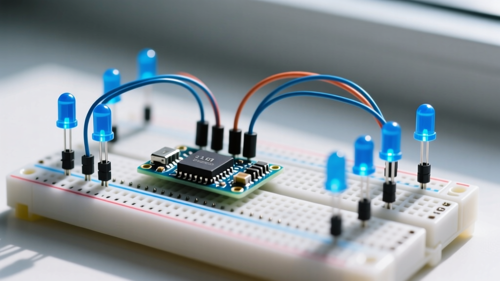
Follow this practical checklist before applying power to your breadboard to ensure component safety and optimal brightness.
- Verify Polarity: Confirm the anode (long leg) connects toward the digital pin and the cathode (short leg) connects to ground.
- Check Resistor Bands: Read the color bands to ensure you have a 220-ohm (Red-Red-Brown-Gold) or 330-ohm (Orange-Orange-Brown-Gold) component, not a zero-ohm jumper.
- Confirm Pin Mode: Ensure your C++ sketch includes
pinMode(pinNumber, OUTPUT);in the setup loop. - Measure Total Draw: If driving multiple diodes, ensure the sum of their currents does not exceed the microcontroller's total ground pin limit (typically 200 milliamperes for the Arduino Uno Rev3).
Conclusion
Selecting the correct arduino led resistor is a straightforward application of Ohm's Law that guarantees the longevity of your microcontroller and the consistency of your light output. By matching the resistor value to the specific forward voltage of your chosen diode color, you eliminate the risk of thermal failure. Your next step is to wire the calculated circuit on a solderless breadboard and verify the actual voltage drop across the diode using a digital multimeter.