
The Reality of Building a Radar with Arduino
Building a radar with Arduino is a foundational project in the maker community. Whether you are constructing the classic sweeping ultrasonic scanner using an SG90 servo and an HC-SR04 sensor, or upgrading to a modern 24GHz mmWave presence detector like the Hi-Link LD2410, the transition from breadboard prototype to reliable instrument is fraught with hidden electrical and software pitfalls. In 2026, while microcontrollers have become faster and sensors more precise, the fundamental physics of power delivery, acoustic multipath interference, and UART serial bottlenecks remain unchanged.
This comprehensive diagnostic guide bypasses basic wiring tutorials and dives straight into the failure modes that cause radar projects to malfunction. We will cover hardware brownouts, non-blocking code architectures, serial buffer overflows, and the specific baud-rate traps associated with modern mmWave modules.
Diagnostic Matrix: Symptom to Root Cause
Before opening the serial monitor or rewriting your sketch, cross-reference your system's behavior with this diagnostic matrix. Identifying the exact failure signature will save hours of blind troubleshooting.
| Symptom | Primary Component | Root Cause | Diagnostic Step / Quick Fix |
|---|---|---|---|
| Servo jitters violently; Arduino resets randomly | SG90 Servo / Power Rail | Voltage brownout exceeding ATmega328P tolerance | Measure 5V rail under load. Move servo to external buck converter. |
| Distance reads 0cm or maxes out at 3000cm | HC-SR04 Ultrasonic | Acoustic multipath or pulseIn() timeout | Add 100nF decoupling cap; switch to NewPing library. |
| Processing IDE visual sweep lags or desyncs | Serial / Processing | Serial buffer overflow; lack of data framing | Implement start/end marker parsing; increase baud rate. |
| mmWave (LD2410) outputs garbage characters | LD2410 / SoftwareSerial | Baud rate mismatch (256000 vs 115200 limit) | Use HardwareSerial or reconfigure sensor via BLE app. |
| Radar detects static objects as moving targets | RCWL-0516 / LD2410 | RF interference or multipath reflection | Shield sensor rear; adjust detection gate thresholds. |
Failure Mode 1: The Servo Sweep Brownout
The most ubiquitous 'radar with Arduino' project utilizes a micro servo to pan an ultrasonic sensor across a 180-degree arc. The most common critical failure is erratic servo jitter accompanied by the Arduino's onboard LED flickering or the MCU resetting entirely.
The Physics of the Failure
An SG90 micro servo costs roughly $3 and is widely used, but it has a stall current that can spike to 650mA when starting or hitting a mechanical bind. When powered directly from the Arduino Uno's 5V pin, this current must pass through the board's linear voltage regulator (often an NCP1117) or the USB polyfuse. The linear regulator will thermally throttle or drop voltage if the draw exceeds 400mA-500mA, causing the 5V rail to sag below the 4.5V minimum required by the ATmega328P's brownout detection (BOD) circuit. The MCU resets, the servo loses its PWM signal, and the system enters a failure loop.
The Definitive Fix
Never power a sweeping servo directly from the Arduino's 5V pin. Instead, use an LM2596 step-down buck converter module (approximately $2) to step down a 9V-12V external wall adapter to a stable 5V.
- Connect the buck converter's 5V and GND directly to the servo's red and brown wires.
- Connect the buck converter's GND to the Arduino's GND to establish a common ground reference.
- Connect the servo's signal wire (orange) to the Arduino's PWM pin (e.g., Pin 9).
Failure Mode 2: Ultrasonic Ghosting and Timeout Errors
When using the HC-SR04 ultrasonic sensor for your radar, you may encounter 'ghost' readings—sudden spikes to 3000cm or drops to 0cm. This is rarely a broken sensor; it is almost always a timing or acoustic reflection issue.
The Problem with pulseIn()
The standard Arduino pulseIn() function is blocking. It halts all code execution while waiting for the echo pin to go HIGH and then LOW. If the ultrasonic pulse scatters into the void and never returns, pulseIn() will wait for the default timeout (usually 1000 milliseconds), freezing your servo sweep and destroying your radar's frame rate.
Implementing Non-Blocking Diagnostics
To resolve this, abandon the default pulseIn() method and adopt the NewPing Library. NewPing utilizes timer interrupts to measure pulse width without blocking the main loop, allowing your servo to continue sweeping smoothly even if an ultrasonic ping is lost.
Expert Tip: Ultrasonic sensors are highly susceptible to power supply noise. Solder a 100nF (0.1µF) ceramic capacitor directly across the VCC and GND pins on the back of the HC-SR04 PCB. This filters out high-frequency switching noise from the Arduino's power rail, stabilizing the sensor's internal comparator and drastically reducing ghost readings.
Failure Mode 3: Processing IDE Visualization Desync
A true radar with Arduino requires a visual interface, typically built in the Processing IDE. A frequent error is the visual sweep lagging behind the physical servo, or the radar 'smearing' across the screen with outdated distance data.
Serial Buffer Overflows
This desync occurs because the Arduino is transmitting data faster than the Processing sketch can read and render it, causing the serial buffer to overflow and drop bytes. When bytes drop, the Processing sketch might read a distance value as an angle, corrupting the visual matrix.
Framing the Data Payload
Do not send raw integers separated by arbitrary commas. Implement a strict data framing protocol using start and end markers. For example, format your serial output as <45,120> where 45 is the angle and 120 is the distance in centimeters.
In Processing, use a readBytesUntil() or custom string parsing function that ignores all incoming serial data until it detects the < character, and stops reading at the > character. This ensures that even if the buffer drops a packet, the next packet will synchronize perfectly, maintaining the integrity of your radar display.
Failure Mode 4: The mmWave UART Trap (LD2410 & LD2450)
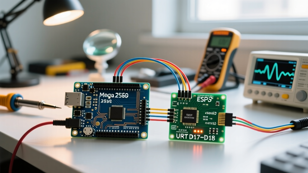
As of 2026, the maker community has largely pivoted from acoustic ultrasonic sensors to 24GHz mmWave radar modules like the Hi-Link LD2410 (for 1D presence) and the LD2450 (for 2D coordinate tracking). These sensors connect via UART (TX/RX). The most catastrophic error makers face when integrating these modules with an Arduino Uno or Nano is receiving endless strings of garbage characters in the serial monitor.
The Baud Rate Bottleneck
Out of the factory, the LD2410 and LD2450 communicate at a default baud rate of 256,000 bps. Makers typically attempt to connect these to digital pins 10 and 11 using the SoftwareSerial library. However, the ATmega328P's software-based serial emulation relies on pin-change interrupts. At baud rates above 57,600 (and especially at 115,200+), the interrupt overhead consumes 100% of the MCU's clock cycles, resulting in massive bit-timing errors and corrupted data frames.
Diagnostic Solutions for mmWave UART
You have two viable paths to resolve this high-speed UART error:
- Use HardwareSerial (The Reliable Method): Connect the mmWave TX/RX pins directly to the Arduino's hardware UART pins (Pin 0 RX and Pin 1 TX). You will need to disconnect these pins every time you upload a new sketch via USB, but the hardware UART can easily handle 256,000 baud without dropping frames.
- Reconfigure the Sensor Baud Rate (The Convenient Method): Download the official Hi-Link 'HLKRadarTool' app on your smartphone. Connect to the LD2410 via its onboard Bluetooth Low Energy (BLE) interface. Navigate to the system settings and permanently lower the UART baud rate to 115,200 or 57,600. Once reconfigured, you can safely use
SoftwareSerialorAltSoftSerialon standard digital pins without overwhelming the ATmega328P.
For those building advanced 2D tracking radars using the LD2450, the data payload is significantly larger. In this scenario, relying on an 8-bit Arduino is a fundamental architectural error. Upgrade to an ESP32-S3 or a Raspberry Pi Pico, which feature multiple hardware UART peripherals and 32-bit architectures capable of parsing the LD2450's high-speed target coordinate streams natively.
Advanced Troubleshooting: RF Multipath Interference
If your mmWave radar is detecting 'phantom' movement when the room is empty, you are experiencing RF multipath interference. The 24GHz signal can bounce off metallic surfaces, ceiling fans, or even HVAC vents, creating Doppler shifts that the sensor interprets as human micro-movements (like breathing).
To diagnose this, use the HLKRadarTool app to view the raw 'Gate Energy' graphs. If you see high energy returns in the distant gates (e.g., Gate 6 or 7) while the room is empty, narrow the sensor's maximum detection gate via the app to physically ignore the back wall. Additionally, place a piece of RF shielding tape or aluminum foil on the rear and sides of the sensor PCB to restrict its field of view strictly to the forward vector.
Summary of Best Practices
Building a reliable radar with Arduino requires respecting the physical limits of both hardware and software. Isolate high-current servo loads from your logic rails, replace blocking timing functions with interrupt-driven libraries, implement strict serial data framing, and never force high-baud-rate mmWave sensors through software-emulated UART pins. By systematically applying these diagnostic frameworks, your radar projects will transition from frustrating prototypes to robust, accurate environmental scanners.
For further reading on serial protocol stability and interrupt management, consult the SparkFun Serial Communication Tutorial to deepen your understanding of microcontroller data bus architectures.