The Reality of Solderless Prototyping
When makers search for how to use breadboard Arduino configurations effectively, they are often met with basic LED-blinking tutorials. However, transitioning from a pre-assembled development board to a custom solderless prototype requires a deep understanding of electrical compatibility, mechanical constraints, and signal integrity. A breadboard is not merely a physical holder; it is an active electrical component with inherent resistance, parasitic capacitance, and current limitations. As of 2026, while surface-mount technology dominates commercial electronics, the DIP (Dual In-line Package) format remains the undisputed king of the maker bench. This compatibility guide explores the exact specifications, failure modes, and best practices for building robust microcontroller circuits without a single drop of solder.
Microcontroller Form Factors: What Actually Fits?
The standard solderless breadboard features a center trench designed specifically to accommodate DIP chips with a 0.3-inch (7.62mm) row spacing. Not all popular development boards respect this footprint. Below is a compatibility matrix for common microcontrollers used in the Arduino ecosystem.
| Microcontroller / Board | Package Type | Breadboard Compatible? | Notes & Workarounds |
|---|---|---|---|
| ATmega328P-PU | DIP-28 | Yes (Perfect Fit) | Leaves 1 row of tie-points free on each side for wiring. |
| ATmega2560-16PU | DIP-40 | Yes (Perfect Fit) | Straddles the center trench exactly; requires extensive wiring. |
| Raspberry Pi Pico (RP2040/RP2350) | DIP-40 Module | Yes (Straddles Trench) | Covers all inner rows; use adjacent power rails for breakout. |
| ESP32 DevKitC V4 | DIP-38 (Wide) | No (Too Wide) | Spans 0.6 inches. Requires two breadboards side-by-side or a custom breakout board. |
| Arduino Nano / Nano Every | Module | Yes (Perfect Fit) | Pre-soldered headers fit standard 0.1" tie-points natively. |
Power Rail Constraints and Contact Resistance
One of the most frequent points of failure when learning how to use breadboard Arduino setups is ignoring the electrical limits of the internal spring clips. According to SparkFun's breadboard anatomy guide, standard tie-points are rated for roughly 1A to 3A maximum. However, the contact resistance is the hidden enemy. Each junction typically introduces 50 to 100 milliohms of resistance.
If you route 500mA through a long power rail with multiple jumper connections, the cumulative voltage drop can easily exceed 0.25V. This causes brownouts, erratic ADC readings, and random microcontroller resets.
Expert Warning: Never route high-current inductive loads (like servo motors, stepper motors, or DC water pumps) directly through breadboard power rails. The voltage spikes and sustained current will degrade the spring clips permanently, leading to intermittent connections. Use the breadboard only for logic-level signals and power external loads via a dedicated perfboard or terminal block.
Wire Gauge Selection
- 22 AWG Solid Core: The industry standard. Fits snugly into standard tie-points. However, inserting and removing 22 AWG wire repeatedly can stretch the internal metal clips, ruining the breadboard over time.
- 24 AWG Solid Core: Highly recommended for dense ATmega328P builds. It exerts less mechanical stress on the contacts while maintaining excellent conductivity for logic signals.
- Stranded Wire: Never use bare stranded wire. The frayed ends will splay inside the tie-point, causing short circuits and permanently jamming the contact mechanism. Always use crimped ferrules if stranded wire is mandatory.
Step-by-Step: Building a Standalone ATmega328P Circuit
To truly master breadboard prototyping, you must know how to build a standalone Arduino using a bare ATmega328P-PU chip (typically priced between $3.50 and $5.00 in 2026). This requires replicating the support circuitry found on an Arduino Uno.
- Place the MCU: Insert the ATmega328P-PU across the center trench. Ensure the notch faces the top of the board (Pin 1 is top-left).
- Clock Source: Insert a 16MHz HC-49S crystal oscillator across pins 9 (XTAL1) and 10 (XTAL2). Add two 22pF ceramic load capacitors from each crystal leg to the ground rail.
- Decoupling Capacitors: This is non-negotiable. Place 100nF (0.1µF) X7R ceramic capacitors physically adjacent to VCC (Pin 7) and AVCC (Pin 20), routing them directly to GND (Pin 8 and Pin 22). This filters high-frequency noise that the breadboard's parasitic inductance will otherwise amplify.
- Reset Pull-Up: Connect a 10kΩ resistor from Pin 1 (PC6/RESET) to the 5V rail. Without this, the microcontroller will remain in a permanent reset state or behave erratically due to floating voltage.
- Power Injection: Connect 5V to Pins 7 and 20. Connect GND to Pins 8 and 22. Refer to the official Arduino power documentation for detailed voltage regulation schematics if you are stepping down from a 9V battery.
USB-to-Serial Adapters: Bridging the Upload Gap
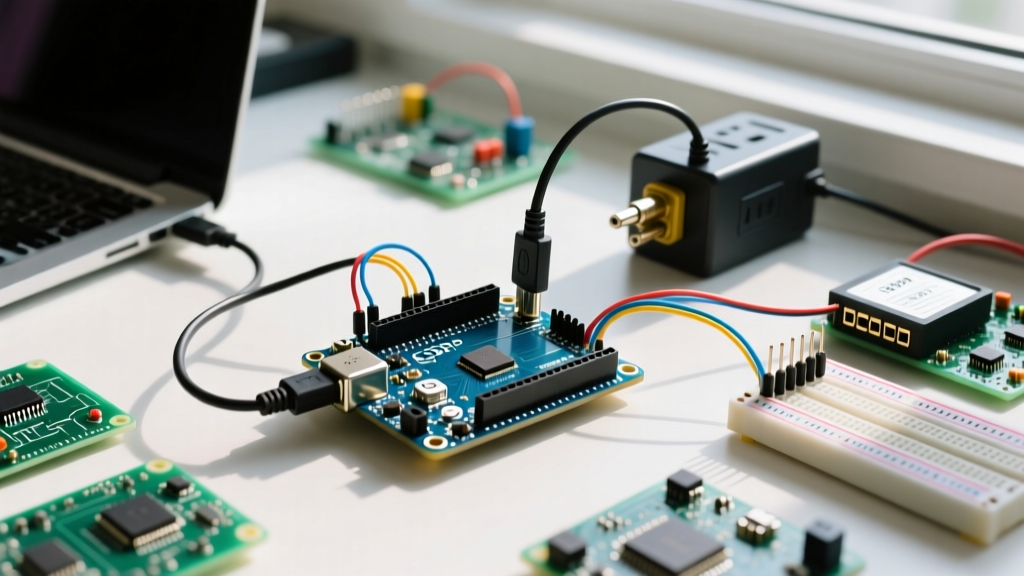
A standalone breadboard Arduino lacks the onboard ATmega16U2 USB-to-Serial converter. To upload sketches via the Arduino IDE, you need an external UART adapter. Not all adapters are created equal regarding compatibility and auto-reset functionality.
Auto-Reset Circuit (The DTR Trick)
The Arduino IDE asserts the DTR (Data Terminal Ready) line when initiating an upload. On a standard Uno, a 100nF capacitor couples this DTR signal to the RESET pin, pulling it low momentarily to trigger the bootloader. To replicate this on a breadboard:
- Connect the DTR pin of your USB-Serial adapter to one leg of a 100nF ceramic capacitor.
- Connect the other leg of the capacitor to Pin 1 (RESET) on the ATmega328P.
- If your adapter only exposes RTS instead of DTR, you will need to manually press a tactile switch connected from RESET to GND exactly when the IDE says "Uploading..."
Signal Integrity: I2C and SPI on Breadboards
High-speed digital protocols are highly susceptible to the physical limitations of solderless environments. Every tie-point and wire on a breadboard introduces roughly 2pF to 5pF of parasitic capacitance. While negligible for a 9600-baud serial connection, this capacitance acts as a low-pass filter on fast digital edges.
When wiring I2C sensors (like the BME280 or MPU6050) on a large breadboard, the bus capacitance can easily exceed 100pF. If you are running I2C at 400kHz (Fast Mode), the standard 10kΩ pull-up resistors will result in a sluggish rise time, causing data corruption. Solution: Drop the I2C pull-up resistors to 2.2kΩ or even 1kΩ to provide more current to charge the parasitic capacitance faster, ensuring sharp square waves. For SPI, keep the MOSI, MISO, and SCK wires under 10cm to prevent crosstalk and clock skew.
Troubleshooting Matrix: Common Breadboard Failures
When your circuit fails to compile, upload, or run, use this diagnostic matrix to isolate the physical layer issues.
| Symptom | Probable Root Cause | Actionable Solution |
|---|---|---|
| AVRDude: "Programmer is not responding" | RX/TX swapped or missing GND reference. | Verify TX on adapter goes to RX on MCU. Ensure a common ground wire exists between the UART adapter and the breadboard. |
| Random resets when a sensor triggers | Voltage drop on the power rail due to sensor current spike. | Add a 100µF electrolytic bulk capacitor across the main power rails near the sensor module. |
| I2C "No Device Found" on scanner | Missing pull-up resistors or excessive bus capacitance. | Install 4.7kΩ pull-ups on SDA/SCL. Shorten jumper wires. Verify sensor address via datasheet. |
| ADC readings fluctuate wildly | Floating AREF pin or lack of analog decoupling. | Place a 100nF capacitor between AREF (Pin 21) and GND. Ensure analog signals share a clean ground path. |
Final Thoughts on Prototyping
Mastering how to use breadboard Arduino setups is a rite of passage for embedded engineers. By respecting the mechanical limits of the tie-points, managing parasitic capacitance, and correctly implementing decoupling and reset circuits, you can build highly reliable prototypes that mirror the behavior of final PCB designs. Always use high-quality 24 AWG solid-core wire, verify your power delivery with a multimeter before inserting sensitive ICs, and remember that a breadboard is a temporary testing ground, not a permanent deployment solution.