
The Engineering Challenge of Off-Grid IoT
Deploying microcontrollers in remote agricultural fields, environmental monitoring stations, or off-grid wildlife cameras requires a robust energy harvesting strategy. Relying on primary lithium cells (like CR123A or Li-SOCl2) is viable for low-duty-cycle deployments, but the recurring cost and environmental impact make arduino solar power systems the superior choice for long-term sustainability. However, simply wiring a 5V solar panel to a development board's VIN pin is a recipe for corrupted flash memory and degraded lithium batteries.
In this comprehensive tutorial, we will design, size, and wire a complete solar power subsystem for an Arduino MKR WAN 1310 LoRa node. We will move beyond generic advice, utilizing exact power budget calculations, real-world 2026 component pricing, and dynamic power path management techniques to ensure your node survives multi-week winter storms.
Step 1: Calculate the True Power Budget
Before selecting a solar panel or battery, you must quantify your energy expenditure. The Arduino MKR WAN 1310 is an excellent low-power candidate, but its current draw varies wildly depending on its state and peripheral usage.
Power State Profiling
Let us assume a standard environmental telemetry profile: the node wakes up every 15 minutes, reads a BME280 sensor via I2C, transmits a 12-byte LoRaWAN payload at 14 dBm, and returns to deep sleep.
| System State | Current Draw | Duration per Cycle | Daily Cycles | Daily Energy (mAh) |
|---|---|---|---|---|
| Deep Sleep (MCU + LoRa) | 12 µA (0.012 mA) | 898 seconds | 96 | 0.28 mAh |
| Active (Sensor Read + MCU) | 18 mA | 1.5 seconds | 96 | 0.72 mAh |
| LoRa TX (14 dBm, SF7) | 110 mA | 0.5 seconds | 96 | 1.46 mAh |
| Total Daily Consumption | Sum of all operational states | 2.46 mAh | ||
Our baseline daily consumption is roughly 2.5 mAh. To account for system inefficiencies, voltage regulator quiescent current, and occasional over-the-air (OTA) firmware updates, we apply a 2.5x safety multiplier, bringing our design target to 6.25 mAh per day.
Step 2: Sizing the Energy Reservoir (Battery)
A solar panel only generates power when exposed to sufficient irradiance. Your battery must bridge the gap during prolonged cloud cover, snow accumulation, or seasonal solstice shifts. According to historical irradiance data from the National Renewable Energy Laboratory (NREL), a location like Seattle, WA, experiences an average of just 1.5 Peak Sun Hours (PSH) per day in December.
Autonomy Calculation
For mission-critical environmental monitoring, we design for 45 days of total darkness autonomy. This ensures the node survives extreme winter weather events without dropping offline.
- Daily Target: 6.25 mAh
- Autonomy Requirement: 45 days
- Raw Capacity Needed: 6.25 mAh × 45 = 281.25 mAh
- Depth of Discharge (DoD) Buffer: Lithium Polymer (LiPo) cells degrade rapidly if discharged below 3.2V. We limit usable capacity to 85%.
- Final Battery Size: 281.25 / 0.85 = 330 mAh
Expert Insight: While a 350 mAh LiPo mathematically satisfies the requirement, physical availability and cold-weather voltage sag dictate a larger buffer. We will select a standard 1200 mAh 3.7V LiPo battery (approx. $9.50 in 2026). This provides over 150 days of autonomy, virtually eliminating the risk of deep-discharge bricking during anomalous weather patterns.
Step 3: Selecting the Solar Panel and Charge Controller
This is where most DIY arduino solar power projects fail. You cannot connect a raw solar panel directly to a LiPo battery. Solar panels output variable voltage (often 6V to 22V open-circuit) depending on irradiance, while LiPo cells require strict constant-current/constant-voltage (CC/CV) charging profiles capping at 4.2V. Overcharging a LiPo cell will cause catastrophic thermal runaway.
Charge Controller Comparison Matrix
| Module | Topology | Max Input | Power Path Mgmt | Price (2026) | Verdict |
|---|---|---|---|---|---|
| Generic TP4056 | Linear | 8V | No | $1.50 | Avoid for solar (requires stable 5V USB input) |
| CN3791 Module | PWM Buck | 28V | No | $4.00 | Good for large 12V panels, poor for low-light IoT |
| Adafruit bq24210 (PID 4755) | Switch-Mode | 20V | Yes (DPPM) | $14.50 | Best for MCU IoT (Harvests low-light efficiently) |
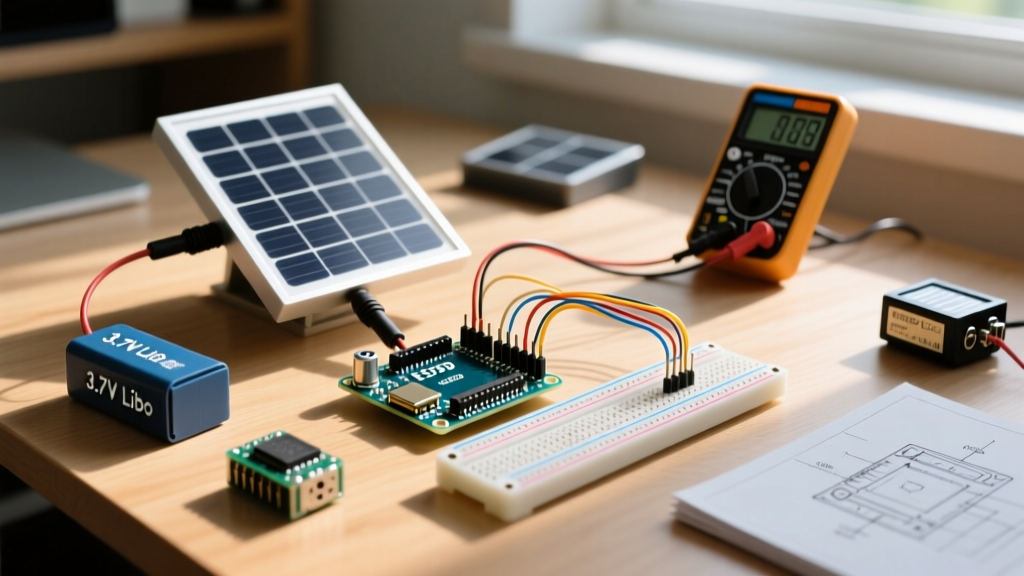
We are selecting the Adafruit Universal USB/Solar Lithium Ion/Polymer charger based on the Texas Instruments bq24210. As detailed in the TI bq24210 datasheet, this IC features Dynamic Power Path Management (DPPM). DPPM allows the solar panel to power the Arduino directly while simultaneously charging the battery. If the panel's output drops (e.g., a cloud passes over), the IC seamlessly supplements the load from the battery without resetting the microcontroller.
Panel Sizing
To replenish our 6.25 mAh daily budget, a 2-Watt, 6-Volt Monocrystalline Epoxy Panel (approx. $12.00) is ideal. In full sun, it generates ~330 mA. Even in the low-light conditions of a Pacific Northwest winter (1.5 PSH), it will yield roughly 150 mAh per day—more than 20 times our daily requirement, ensuring the 1200 mAh battery remains fully topped off.
Step 4: Wiring the Subsystem
Proper wiring is critical to minimize voltage drop and prevent ground loops. Keep wire runs between the charge controller, battery, and MCU as short as possible (under 10 cm). Use 22 AWG silicone-stranded wire for flexibility and low resistance.
- Solar Panel to Charge Controller: Solder the panel's positive (red) and negative (black) wires to the
VINandGNDpads on the Adafruit bq24210 breakout. Note: Always connect the battery before connecting the solar panel to prevent the IC from misreading the open-circuit voltage. - Battery Connection: Connect the 1200 mAh LiPo's JST-PH 2.0mm connector to the
BATport on the bq24210. Ensure polarity is strictly observed; reversed polarity will instantly destroy the charging IC. - Load Output to Arduino: Connect the bq24210's
OUTandGNDpads to the Arduino MKR WAN 1310'sVINandGNDpins. Do not use the 5V pin. TheVINpin routes through the board's internal AP2112K-3.3 voltage regulator, which can safely accept the 3.7V to 4.2V LiPo range. - Telemetry Wiring (Optional but Recommended): Run a wire from the bq24210's
CHRG(Charge Status) pin to a digital input on the Arduino (e.g., Pin 5). This allows your firmware to log whether the panel is actively harvesting energy, providing valuable remote diagnostics.
Hardware Warning: Never connect a USB cable to the Arduino MKR WAN 1310 while the solar panel is exposed to bright sunlight and feeding the VIN pin. Back-feeding voltage into the board's USB power multiplexer can damage your host computer's USB port. Always cover the panel during firmware flashing.
Step 5: Firmware Optimization for Solar Harvesting
Hardware is only half the equation. If your firmware blocks the main thread with delay() functions, your power budget will skyrocket, and the solar panel will fail to keep up. You must utilize the ArduinoLowPower library to invoke hardware sleep states.
According to the official Arduino MKR WAN 1310 documentation, the SAMD21 microcontroller supports multiple sleep modes. For solar IoT nodes, we utilize Idle and Standby modes.
#include <ArduinoLowPower.h>
#include <MKRWAN.h>

LoRaModem modem(Serial1);

void setup() {
  // Initialize LoRa and Sensors here
  // Ensure USB serial is not left hanging, which prevents deep sleep
  Serial.end();
}

void loop() {
  // 1. Wake up and perform sensor read / LoRa TX
  transmitTelemetry();

  // 2. Put LoRa module to sleep
  modem.sleep();

  // 3. Enter Standby mode for 15 minutes (900,000 ms)
  // The RTC (Real Time Clock) remains active to wake the MCU
  LowPower.sleep(900000);
}
Edge Cases and Real-World Failure Modes
When deploying arduino solar power systems in the field, theoretical math often collides with environmental reality. Anticipate these specific failure modes:
1. The Winter Solstice Snow Cover
If your node is deployed in a region with heavy snow, a 2W panel mounted flat will become buried, dropping generation to zero. Solution: Mount the solar panel at an angle equal to your local latitude + 15 degrees. This steep angle encourages snow shedding and optimizes the capture angle for the low winter sun.
2. Cold Temperature Voltage Sag
LiPo batteries suffer from increased internal resistance at freezing temperatures. At -10°C, a fully charged 3.7V LiPo may sag to 3.3V under a 100mA LoRa TX load, triggering the Arduino's Brown-Out Detector (BOD) and causing a continuous reboot loop. Solution: In your firmware, read the internal battery voltage via an analog divider before initiating a LoRa transmission. If the voltage is below 3.5V, skip the transmission and return to sleep to allow the solar panel to warm and charge the cell.
3. Panel Shading and Hotspots
Even partial shading (e.g., a single tree branch covering 10% of a monocrystalline cell) can drop a panel's output by up to 50% due to the series-wired nature of the cells. Furthermore, shaded cells can become reverse-biased and dissipate power as heat, creating permanent hotspot damage. Solution: If deploying under a forest canopy, use amorphous silicon (a-Si) or SunPower Maxeon back-contact panels, which handle partial shading significantly better than standard poly/monocrystalline epoxy panels, albeit at a higher cost per watt.
Final Bill of Materials (BOM)
| Component | Specification | Est. Cost |
|---|---|---|
| Microcontroller | Arduino MKR WAN 1310 (LoRa) | $55.00 |
| Solar Panel | 2W 6V Monocrystalline Epoxy | $12.00 |
| Charge Controller | Adafruit bq24210 Breakout (PID 4755) | $14.50 |
| Battery | 1200mAh 3.7V LiPo (JST-PH) | $9.50 |
| Total Node Cost | $91.00 (Excluding sensors/enclosure) | |
By rigorously calculating your power budget, utilizing a DPPM-enabled charge controller, and writing non-blocking sleep firmware, your Arduino solar power deployment will transition from a fragile weekend prototype to a resilient, multi-year commercial-grade IoT asset.