
Why Your Microcontroller Needs an External RTC
While the Arduino's internal millis() function is excellent for short-term delays and non-blocking timing, it is fundamentally unsuited for long-term timekeeping. The internal ceramic resonator or crystal oscillator is subject to temperature-induced drift, typically losing or gaining several seconds per day. Furthermore, every time the board loses power or resets, the internal timer drops to zero. When building data loggers, automated greenhouse controllers, or scheduled lighting systems, configuring an Arduino with RTC module hardware is mandatory to maintain persistent, wall-clock time.
Hardware Selection: DS3231 vs DS1307
The market is dominated by two primary I2C Real-Time Clock ICs: the older DS1307 and the highly accurate DS3231. As of 2026, supply chain shifts have altered the pricing landscape, making the choice between them more nuanced than simply picking the cheapest option.
| Feature | DS1307 | DS3231 (and DS3231SN) |
|---|---|---|
| Oscillator Type | External 32.768 kHz Crystal | Internal TCXO (Temp-Compensated) |
| Accuracy | ±20 ppm (approx. 1 min/month) | ±2 ppm (approx. 1 min/year) |
| I2C Address | 0x68 | 0x68 |
| Module Price (2026) | ~$0.90 (Clone) | ~$1.40 (Clone) / $5.50+ (Genuine) |
| Alarm / SQW Output | Basic Square Wave only | 2 Alarms + Programmable SQW |
Expert Recommendation: Unless you are building a cost-sensitive toy where a minute of drift per month is acceptable, always choose the DS3231. The internal MEMS resonator and temperature compensation circuitry eliminate the need for manual calibration. According to the Analog Devices DS3231 Datasheet, the TCXO actively adjusts the oscillator frequency based on an internal temperature sensor, ensuring stability across -40°C to +85°C ranges.
I2C Wiring and Pinout Matrix
RTC modules communicate via the I2C bus. While the SDA (data) and SCL (clock) pins vary across different Arduino architectures, the power and ground connections remain universal. Always power the RTC module with 5V (VCC) if you are using a standard 5V Arduino Uno or Mega, as the onboard logic level shifters on most breakout boards require 5V to operate correctly and pass 3.3V signals to the chip.
| Board | SDA Pin | SCL Pin | Notes |
|---|---|---|---|
| Arduino Uno / Nano | A4 | A5 | Also available on dedicated SDA/SCL header pins |
| Arduino Mega 2560 | 20 | 21 | Do not use A4/A5 on Mega for I2C |
| Arduino Leonardo | 2 | 3 | Also available on dedicated header pins |
| ESP32 (Standard) | GPIO 21 | GPIO 22 | Requires 3.3V VCC, do not use 5V |
CRITICAL: The ZS-042 Breakout Board Battery Trap
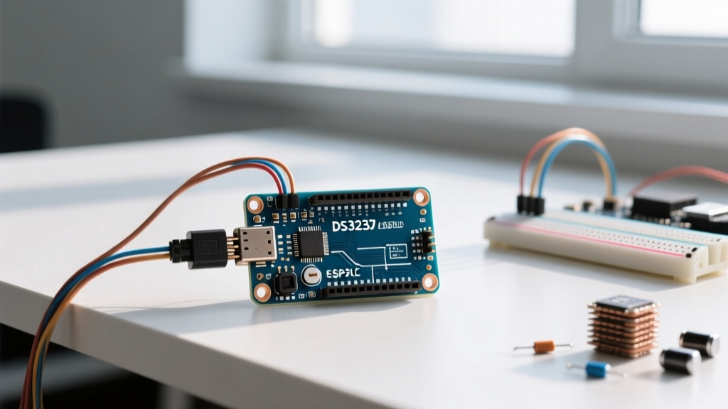
If you purchase a cheap DS3231 or DS1307 module, it will likely be the ubiquitous blue 'ZS-042' breakout board. This board contains a dangerous design flaw regarding battery backup that ruins projects and can cause hardware damage.
WARNING: The ZS-042 board includes a charging circuit designed for LIR2032 rechargeable lithium-ion coin cells. It features a 1N4148 diode and a 200Ω resistor. If you insert a standard, non-rechargeable CR2032 battery, the board will attempt to charge it. This will rapidly deplete the CR2032, cause severe voltage drops on the I2C bus, and in extreme cases, cause the battery to vent or rupture.
The Fix: If you intend to use a standard CR2032 (which is highly recommended for multi-year backup life), you must disable the charging circuit. Locate the small surface-mount diode (D1) or the 200Ω resistor near the battery holder on the top-left of the module. Use a soldering iron to carefully remove the diode, or simply cut the trace connecting the VCC line to the battery positive terminal. This ensures the battery only supplies power when VCC drops below the diode drop threshold, preserving the CR2032 for up to 8 years.
Software Configuration with RTClib
While you can manually write hex values to the RTC registers via the Arduino Wire Library, handling BCD (Binary-Coded Decimal) conversions and leap year logic is tedious. The industry standard is the Adafruit RTClib. Install it via the Arduino IDE Library Manager.
Step 1: Setting the Time Exactly Once
A common beginner mistake is leaving the 'set time' function in the main loop() or even at the top of setup(). If the Arduino resets, the RTC will be overwritten with the compile time, losing accuracy. Use the following configuration pattern to set the time once, then comment out the setting line.
#include <Wire.h>
#include <RTClib.h>

RTC_DS3231 rtc;

void setup() {
  Serial.begin(9600);
  Wire.begin();

  if (!rtc.begin()) {
    Serial.println("Couldn't find RTC");
    while (1); // Halt execution
  }

  if (rtc.lostPower()) {
    Serial.println("RTC lost power, let's set the time!");
    // Uncomment the line below to set the RTC to the exact compile time
    // rtc.adjust(DateTime(F(__DATE__), F(__TIME__)));

    // OR set manually: Year, Month, Day, Hour, Minute, Second
    rtc.adjust(DateTime(2026, 10, 24, 14, 30, 0));
  }
}

void loop() {
  DateTime now = rtc.now();
  Serial.printf("%04d-%02d-%02d %02d:%02d:%02d\n",
                now.year(), now.month(), now.day(),
                now.hour(), now.minute(), now.second());
  delay(1000);
}
Advanced I2C Troubleshooting and Edge Cases
Even with perfect wiring, I2C communication with RTC modules can fail in complex builds. Here are the specific failure modes and how to resolve them.
1. I2C Bus Capacitance and Pull-Up Resistors
The I2C specification limits bus capacitance to 400pF. If you have long wires (over 30cm) or multiple sensors on the same bus alongside your RTC, the signal edges will degrade, causing the Arduino to read corrupted BCD data (e.g., returning '165' for the hour). Most RTC breakout boards include 4.7kΩ pull-up resistors on SDA and SCL. If you have three or more modules with onboard pull-ups, the parallel resistance drops too low (e.g., three 4.7kΩ resistors in parallel equal ~1.5kΩ), which can overwhelm the microcontroller's open-drain sinks. Solution: Desolder or cut the traces to the pull-up resistors on all but one device on the I2C bus, or use an active I2C bus extender like the PCA9600.
2. The VCC vs VBAT Switching Glitch
The DS3231 features an internal power-sense circuit that switches to VBAT (battery) when VCC drops below approximately 2.5V. However, if your Arduino project uses a lithium-ion battery that sags to 3.0V under heavy load (like a motor starting), the RTC might experience brownouts without triggering the VBAT switchover, corrupting the time registers. Solution: Place a 100µF decoupling capacitor directly across the VCC and GND pins of the RTC module to buffer transient voltage drops.
3. Handling the Unix Epoch and 2038 Problem
When logging data, it is often easier to store time as a Unix timestamp (seconds since Jan 1, 1970) rather than individual bytes for year, month, and day. RTClib handles this gracefully via now.unixtime(). However, be aware that standard 32-bit signed integers will overflow in the year 2038. If you are designing a long-term industrial installation in 2026 that will run for 15+ years, ensure your logging database or SD card formatting uses 64-bit integers (uint64_t or long long) to store the epoch timestamps.
Summary Checklist for Deployment
- Verify Hardware: Confirm you are using a DS3231 for temperature-compensated accuracy.
- Battery Safety: Remove the charging diode on ZS-042 clone boards before inserting a CR2032.
- Wiring: Check SDA/SCL pins against your specific microcontroller matrix.
- Software: Set the time once using
rtc.adjust(), then comment the line out and re-upload. - Bus Integrity: Ensure total I2C pull-up resistance remains between 2.2kΩ and 4.7kΩ.
By addressing the physical hardware quirks of clone boards and respecting the electrical limits of the I2C bus, your Arduino with RTC module will maintain flawless, persistent timekeeping for years without manual intervention.