
Beyond the Arduino vs Pi Debate: A Hardware Compatibility Masterclass
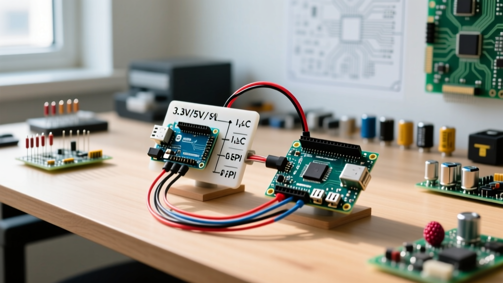
The maker community often frames the Arduino vs Pi discussion as a strict either-or proposition. However, advanced embedded systems frequently demand the real-time deterministic control of a microcontroller alongside the heavy computational lifting of a single-board computer (SBC). When designing hybrid architectures, understanding the electrical and protocol-level compatibility between these two ecosystems is critical to prevent silicon damage and ensure reliable data throughput.
In 2026, the landscape has evolved. The Raspberry Pi 5 features the custom RP1 I/O controller, altering GPIO behavior, while the Arduino Uno R4 series utilizes the Renesas RA4M1 ARM Cortex-M4, introducing 12-bit ADCs and native USB-C. This guide bypasses the basic 'which is better' rhetoric and dives deep into the electrical engineering realities of interfacing Arduino boards with Raspberry Pi hardware.
Core Architecture & Electrical Specifications
Before wiring a single jumper cable, you must understand the fundamental electrical boundaries. The most common point of failure in hybrid builds is ignoring logic level thresholds and power rail tolerances.
| Specification | Raspberry Pi 5 (BCM2712 / RP1) | Arduino Uno R4 Minima | Arduino Nano 33 IoT |
|---|---|---|---|
| Primary Logic Level | 3.3V (Strict) | 5V | 3.3V |
| ADC Resolution | None (Requires external IC) | 12-bit (0-4095) | 12-bit (0-4095) |
| Default I2C Clock | 100 kHz / 400 kHz | 100 kHz | 100 kHz |
| Max GPIO Sink/Source | ~16mA per pin (RP1 dependent) | 20mA per pin | 7mA per pin |
| Real-Time OS / Bare Metal | No (Linux Kernel latency) | Yes (Deterministic) | Yes (Deterministic) |
The 5V vs 3.3V Logic Level Clash
If you are interfacing a 5V Arduino (like the Uno R4 or Mega 2560) with any Raspberry Pi model, direct connection will destroy the Pi's GPIO pins. The Pi's RP1 or BCM SoC pins are not 5V tolerant. Injecting 5V into a Pi GPIO pin will forward-bias the internal ESD protection diodes, causing thermal runaway and permanent silicon damage.
Choosing the Right Level Shifter
Not all logic level shifters are created equal. The choice depends heavily on the communication protocol you are bridging:
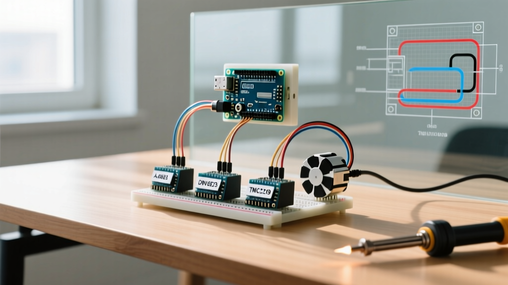
- For I2C (Bidirectional Open-Drain): Use a MOSFET-based shifter like the BSS138 breakout board. I2C requires open-drain architectures. Standard push-pull shifters will cause bus contention and data corruption.
- For SPI and UART (Push-Pull): Use an auto-directional voltage translator like the TXB0108E or TXS0108E. These ICs handle the rapid edge transitions required for SPI clocks exceeding 1 MHz, which MOSFET-based shifters struggle with due to parasitic gate capacitance.
- For Analog Signals: Do not use digital shifters. Use an operational amplifier configured as a non-inverting attenuator (e.g., LMV321) to scale a 0-5V analog sensor output down to the 0-3.3V range required by an external ADC connected to the Pi.
Critical Edge Case: When using the TXB0108E for SPI, ensure the trace lengths on your custom PCB or breadboard are under 10cm. The TXB0108E has a one-shot edge-rate accelerator that can trigger false oscillations if it detects long-wire capacitive loads exceeding 50pF.
Shield and HAT Interoperability
A frequent question in the Arduino vs Pi compatibility sphere is whether Arduino Shields can be stacked onto a Raspberry Pi, or vice versa. The short answer is no, but the engineering reasons are specific.
Physical vs. Electrical Pinouts
While the Raspberry Pi 40-pin header and the Arduino 2x13 female headers share a 0.1-inch (2.54mm) pitch, the pin assignments are entirely arbitrary relative to one another. Furthermore, Arduino shields route the 5V VIN pin to specific headers to power motor drivers and relays. If you force an Arduino shield onto a Pi GPIO header using a generic ribbon cable adapter, you risk feeding 5V directly into the Pi's 3.3V logic rail or backfeeding the Pi's 5V USB-C power input, potentially bypassing the Pi's polyfuse and damaging the PMIC (Power Management IC).
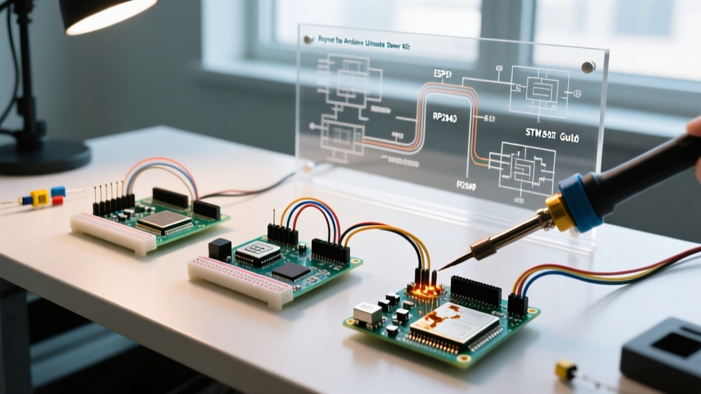
The Solution: For hybrid projects, abandon direct stacking. Instead, use a structured interconnect approach. Mount the Pi and Arduino side-by-side on a custom acrylic chassis or DIN rail, and route communications via a dedicated 4-pin or 6-pin JST-PH cable carrying only VCC, GND, TX, and RX.
Bridging Communication Protocols
When combining the vision processing capabilities of the Pi with the motor control of the Arduino, you must select the right bus. According to the official Arduino hardware documentation, the Uno R4 features expanded peripheral support, making protocol bridging more robust than older AVR boards.
UART (Serial) Bridging
UART is the most forgiving protocol for hybrid setups. To connect a Pi to an Arduino via UART:
- Connect Pi GPIO 14 (TXD) to Arduino RX (via level shifter if 5V).
- Connect Pi GPIO 15 (RXD) to Arduino TX.
- Crucially, connect the GND pins of both boards to establish a common reference plane.
Pi 5 Specifics: The Raspberry Pi 5 routes UART through the RP1 southbridge. Ensure you are targeting the correct device tree overlay in /boot/firmware/config.txt by enabling dtparam=uart0=on. The default baud rate should be set to 115200 on both the Pi's /dev/ttyAMA0 and the Arduino's Serial.begin(115200) to prevent framing errors.
I2C Bus Contention and Pull-Up Resistors
I2C is notoriously problematic in Arduino vs Pi hybrid builds due to pull-up resistor conflicts. The I2C specification, as detailed in the NXP I2C-bus specification and user manual, requires pull-up resistors on SDA and SCL lines.
- The Raspberry Pi has fixed 1.8kΩ pull-up resistors tied to its internal 3.3V rail on pins 3 and 5.
- Many Arduino breakout boards (like the Adafruit BME280) also feature 10kΩ pull-up resistors tied to 5V.
If you wire them together directly, the Arduino's 5V pull-ups will backfeed 5V into the Pi's 3.3V I2C bus. You must physically remove or desolder the pull-up resistors on the 5V Arduino peripherals before connecting them to a Pi's I2C bus, relying solely on the Pi's 3.3V pull-ups (provided the total bus capacitance remains under 400pF).
SPI and Linux Kernel Latency
While SPI offers higher bandwidth than I2C, using the Raspberry Pi as an SPI Master to control an Arduino SPI Slave introduces Linux kernel jitter. The Pi's OS can interrupt the SPI clock generation to handle background tasks, causing the Arduino's SPI interrupt service routine (ISR) to time out or drop bytes. If you require strict, microsecond-accurate SPI clocking (e.g., for high-speed ADC sampling), configure the Arduino as the SPI Master and the Pi as the SPI Slave, allowing the bare-metal MCU to dictate the clock timing.
Designing the Ultimate Hybrid Architecture
The most successful embedded systems do not view the Arduino vs Pi dynamic as a competition, but as a symbiotic relationship. Referencing the Raspberry Pi compute architecture guidelines, offloading real-time tasks to an MCU is a recommended pattern for industrial applications.
The 'Brain and Brainstem' Pattern
- The Brain (Raspberry Pi 5): Handles Wi-Fi 6 / Ethernet networking, MQTT brokering, computer vision (OpenCV), and logging to an NVMe SSD via the PCIe lane. It operates on a high-level event loop.
- The Brainstem (Arduino Uno R4 / Teensy 4.1): Handles sub-millisecond PID control loops for stepper motors, reads quadrature encoders, and monitors hardware limit switches. It operates on hardware timer interrupts.
By separating these domains, a kernel panic or Wi-Fi dropout on the Pi will not cause the robotic arm controlled by the Arduino to lose its positional holding torque.
Frequently Asked Questions (FAQ)
Can I power the Raspberry Pi from the Arduino's 5V pin?
No. The Raspberry Pi 5 can draw upwards of 5A (25W) under peak load. The Arduino's onboard 5V linear regulator or USB-C trace is typically rated for less than 1A. Attempting to backfeed power from an Arduino 5V pin to a Pi's GPIO 5V pins will instantly vaporize the Arduino's PCB traces or trigger its thermal shutdown. Always use a dedicated, high-amperage buck converter (like an LM2596 module set to 5.1V) to power both boards from a common 12V or 24V DC supply.
Is the Arduino Nano 33 IoT safer to connect to a Pi?
Yes, from a voltage perspective. Because the Nano 33 IoT (based on the SAMD21 Cortex-M0+) operates natively at 3.3V, you can connect its GPIO, I2C, and SPI pins directly to the Raspberry Pi without logic level shifters. However, you must still ensure that no external 5V sensors are attached to the Nano's pins, as the SAMD21 is just as sensitive to 5V overvoltage as the Pi.
How do I handle common ground issues between the two boards?
Ground loops can introduce noise into analog readings. If both the Pi and Arduino are powered by separate AC-DC wall adapters, connecting their GND pins can create a ground loop. To solve this, power both boards from a single, centralized DC-DC power supply, ensuring a star-ground topology where the GND of the power supply connects independently to the Pi and the Arduino, rather than daisy-chaining the ground connection from one board to the other.