
The Hidden Complexities of the Arduino Pro Micro Pinout
The Arduino Pro Micro—and the ubiquitous SparkFun-compatible clones that dominate the maker market—is a marvel of compact engineering. Built around the ATmega32U4 microcontroller, it offers native USB capabilities and a footprint small enough to embed in custom keyboards, macro pads, and wearable tech. However, its dense silkscreen and unique architecture make the arduino pro micro pinout a frequent source of catastrophic wiring mistakes and baffling upload errors.
Unlike the standard ATmega328P-based Arduino Uno, the Pro Micro routes its USB data lines directly to the microcontroller's D+ and D- pins. Furthermore, its power regulation scheme and I2C bus mapping deviate sharply from the standard 'Uno' mental model most makers develop. In this diagnostic guide, we will dissect the most common hardware and software failures caused by pinout misinterpretation, providing exact multimeter tests and recovery procedures to save your board from the e-waste bin.
The RAW vs. VCC Trap: Diagnosing Power Rail Destruction
The single most common fatal error when working with the Pro Micro pinout is confusing the RAW pin with the VCC pin. On a standard Arduino Uno, you can safely feed 7-12V into the barrel jack or the Vin pin. On the Pro Micro, the power topology is entirely different and unforgiving.
Critical Failure Mode: Feeding anything above 5.5V (or 3.8V on 3.3V variants) directly into theVCCpin will instantly destroy the ATmega32U4 silicon. TheVCCpin is an output from the onboard regulator or a direct passthrough from USB 5V. It is not a high-voltage input.
Anatomy of the Power Pins
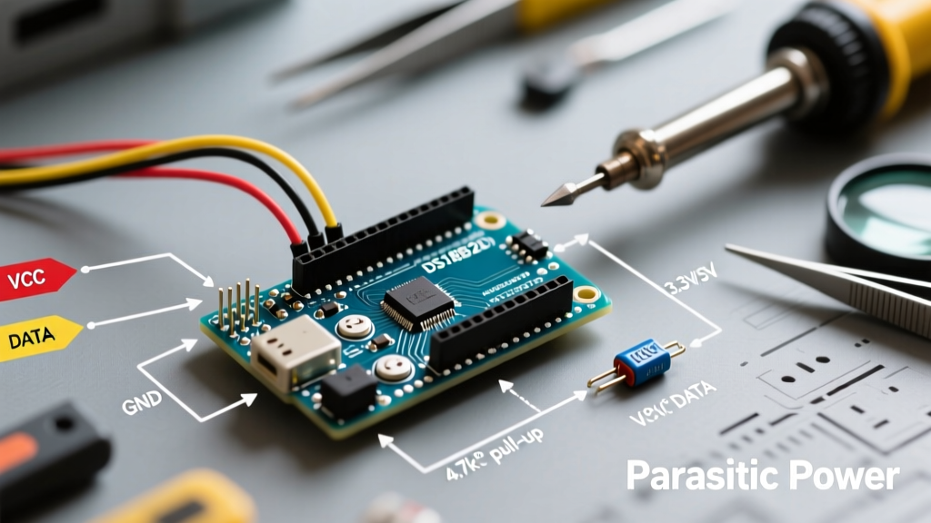
- RAW: This is the input to the onboard voltage regulator (typically a MIC5219 SOT-23-5 LDO on quality clones). It accepts 5V to 12V (though keeping it under 9V is recommended to prevent the LDO from overheating, as it lacks a heatsink and will thermally throttle or fail past 150mA of continuous draw).
- VCC: This is the regulated output. If you power the board via USB, VCC outputs 5V. If you power via RAW, VCC outputs the regulated voltage. You can use VCC as a 5V input to bypass the regulator entirely, but only if your external supply is exactly 5V ± 5%.
- GND: The common ground reference, tied to the USB shield and the regulator's ground pad.
Diagnostic Steps for a 'Dead' Board
If your Pro Micro shows no signs of life (no power LED, no USB enumeration), perform this diagnostic sequence:
- Visual Inspection: Check the MIC5219 regulator near the USB port. If the epoxy is cracked or discolored, it has been subjected to overvoltage or excessive thermal load.
- Continuity Test: Set your multimeter to continuity mode. Place probes on
VCCandGND. A dead short indicates the ATmega32U4 internal voltage rails have blown, usually from back-feeding >5.5V into VCC. - Voltage Drop Test: Power the board via USB. Measure between
VCCandGND. It should read exactly 4.8V to 5.1V. If it reads 0V but the USB connector shell shows 5V against GND, the polyfuse (usually a 500mA PTC) or the VCC trace has failed.
Native USB & The 'Missing' Reset Button: Upload Errors
Because the ATmega32U4 handles USB natively, there is no secondary serial-to-USB chip (like the ATmega16U2 on the Uno). This means if your sketch crashes the USB stack, or if you flood the serial buffer, the board will disappear from your operating system's device manager. The Arduino IDE will throw errors like "Device Descriptor Request Failed" or "Board at port X is not responding".
Compounding this issue, the standard Pro Micro pinout does not include a physical reset button. To enter the bootloader, the board relies on a software trigger: a 1200 bps serial connection that is opened and immediately closed.
Recovering a 'Bricked' Pro Micro
When the IDE fails to upload and the port vanishes, use this hardware-assisted diagnostic recovery method:
- The RST-GND Double Tap: Using a jumper wire, briefly short the
RSTpin to anyGNDpin. Do this twice in rapid succession (within half a second). This forces the ATmega32U4 bootloader to start and hold the COM port open for exactly 8 seconds. - Timing the Upload: In the Arduino IDE, click 'Upload'. The moment the console says "Uploading...", perform the double-tap reset. The IDE will catch the bootloader port and flash the new, non-crashing sketch.
- Permanent Fix: Solder a 6x6mm tactile microswitch between the
RSTandGNDpads on the Pro Micro pinout. This $0.10 modification saves hours of future troubleshooting.
For a deeper understanding of the native USB architecture, refer to the official Arduino Micro documentation, which shares the identical ATmega32U4 schematic and bootloader behavior.
I2C and SPI Mapping: Why Your Sensors Fail to Initialize
Makers transitioning from the Arduino Uno to the Pro Micro frequently encounter I2C communication failures. When running an I2C scanner sketch, OLED displays and BME280 sensors simply do not appear. The root cause is almost always a false assumption about the arduino pro micro pinout regarding the TWI (Two-Wire Interface) bus.
| Protocol | Arduino Uno Pins | Pro Micro (ATmega32U4) Pins | Common Diagnostic Symptom |
|---|---|---|---|
| I2C (SDA) | A4 | D2 (Digital Pin 2) | I2C Scanner finds 0 devices; OLED stays blank. |
| I2C (SCL) | A5 | D3 (Digital Pin 3) | Same as above; pull-up resistors on A4/A5 do nothing. |
| SPI (MOSI) | D11 | D16 (or ICSP Header) | SD cards fail to mount; NRF24L01 won't transmit. |
| SPI (MISO) | D12 | D14 (or ICSP Header) | SPI read operations return 0xFF or 0x00. |
| SPI (SCK) | D13 | D15 (or ICSP Header) | Clock signal missing on oscilloscope. |
Reference: Pin mapping verified against the Microchip ATmega32U4 Datasheet (Section 13.2, Port D Alternate Functions).
Fixing I2C Pull-Up Resistor Errors
The Pro Micro does not always include onboard I2C pull-up resistors, depending on the specific clone manufacturer. If your I2C devices are wired correctly to D2 and D3 but still fail, use an oscilloscope or logic analyzer to check the SDA/SCL lines. If the high state is floating or rising too slowly (RC time constant issues), you must add external 4.7kΩ pull-up resistors between VCC and the SDA/SCL lines. The SparkFun Pro Micro Hookup Guide highly recommends verifying pull-ups when chaining multiple 3.3V sensors on the 5V Pro Micro variant.
Analog Pin Quirks and Digital Mapping
The Pro Micro exposes 12 analog inputs, but their physical layout and digital aliases cause frequent coding errors. Pins A0 through A3 are located on the bottom right of the board. However, A6 through A11 do not have dedicated physical pads labeled with an 'A' prefix; they are shared with digital pins D4, D6, D8, D9, D10, and D12.
Diagnostic Tip: If you are trying to read an analog sensor and getting erratic, floating values (e.g., jumping between 0 and 1023), ensure you are using the correct analogRead() syntax. Use analogRead(A0) rather than analogRead(18). Furthermore, verify that the pin you are using is not internally tied to the RX/TX LEDs. On the Pro Micro, the RX LED is hardcoded to D17 (RXI) and the TX LED to D30 (TXO). Attempting to use these pins for high-frequency PWM or analog reading will yield corrupted data due to the LED circuit's current draw.
Troubleshooting Matrix: Quick Diagnostic Reference
Use this matrix to rapidly isolate pinout and configuration errors during your build process.
| Observed Symptom | Probable Pinout / Wiring Error | Corrective Action |
|---|---|---|
| Board gets extremely hot to the touch immediately upon power-up. | Input voltage >5.5V applied to VCC instead of RAW. |
Disconnect immediately. Check MIC5219 and ATmega32U4 for shorts. Board is likely destroyed. |
| USB enumerates, but IDE says 'Port not found' during upload. | User sketch crashed USB stack; no hardware reset available. | Perform the RST-GND double-tap exactly when IDE says 'Uploading...'. |
| I2C devices not detected by scanner sketch. | Wired to A4/A5 (Uno habit) instead of D2 (SDA) / D3 (SCL). | Rewire SDA to D2, SCL to D3. Add 4.7k pull-ups if missing. |
| Serial Monitor prints garbage characters. | Baud rate mismatch, or reading hardware UART (D0/D1) while expecting USB Serial. | Use Serial.begin() for USB. Use Serial1.begin() for hardware pins D0 (RX) and D1 (TX). |
| Erratic analog readings on A0-A3. | Floating ground reference or missing common ground with sensor. | Verify GND continuity between Pro Micro and sensor module. |
Summary
Mastering the arduino pro micro pinout requires unlearning a few habits picked up from larger, more forgiving development boards. By respecting the strict voltage boundaries of the RAW and VCC pins, understanding the native USB bootloader recovery process, and correctly mapping the I2C bus to D2 and D3, you can eliminate 95% of the hardware and upload errors associated with this powerful microcontroller. Always keep a tactile reset switch and a multimeter on your bench when prototyping with the Pro Micro.