
The Electrical Reality: Beyond the Basic digitalRead()
The digitalRead() function is often the first input method a maker learns, yet it remains a primary source of intermittent bugs in deployed embedded systems. While the Arduino IDE abstracts this function into a simple HIGH or LOW return, the underlying microcontroller is actually measuring analog voltage against specific hardware thresholds. Misconfiguring the pin mode, ignoring logic level differences between 5V and 3.3V architectures, or failing to account for mechanical switch bounce will result in erratic behavior. This configuration guide moves beyond the basic blink sketch to explore the electrical realities of reading digital inputs in 2026, covering ATmega328P (Uno R3), AVR-based Uno R4, and ESP32-WROOM-32 architectures.
Voltage Thresholds: What Constitutes HIGH vs LOW?
A microcontroller does not have a single "trip wire" voltage. Instead, it defines a Low-Level Input Voltage (VIL) and a High-Level Input Voltage (VIH). Any voltage falling between these two thresholds is considered an undefined state and can cause the digitalRead() function to oscillate wildly or draw excess current through the input buffer.
| Microcontroller (Board) | VCC / Logic Level | VIL (Max for LOW) | VIH (Min for HIGH) | Undefined Danger Zone |
|---|---|---|---|---|
| ATmega328P (Arduino Uno R3) | 5.0V | 1.5V (0.3 VCC) | 3.0V (0.6 VCC) | 1.51V to 2.99V |
| ESP32-WROOM-32 | 3.3V | 0.8V | 2.0V | 0.81V to 1.99V |
| RP2040 (Raspberry Pi Pico) | 3.3V | 1.0V | 2.0V | 1.01V to 1.99V |
Note: Never feed a 5V signal directly into an ESP32 or Pico GPIO pin. While the digitalRead() function will register a HIGH, the absolute maximum rating of the silicon will be exceeded, eventually destroying the input protection diodes.
Configuring Pin Modes: The Floating Pin Problem
Before calling digitalRead(pin), you must configure the pin using pinMode(). If a pin is left in its default high-impedance state (or explicitly set to INPUT without an external circuit), it becomes a "floating pin." A floating pin acts as an antenna, picking up electromagnetic interference (EMI) from nearby AC mains, switching power supplies, or even your finger. This results in phantom triggers.
Critical Warning: Never leave unused digital pins configured asINPUTand unconnected in a noisy industrial or automotive environment. Configure unused pins asOUTPUTand drive them LOW, or enable internal pull-ups to prevent parasitic power draw and erratic logic states.
INPUT vs INPUT_PULLUP: The Resistor Dilemma
To prevent floating states, a pin must be biased to a known voltage. According to the SparkFun Pull-Up Resistor Tutorial, this is achieved using resistors. The Arduino architecture provides a massive shortcut: the INPUT_PULLUP mode.
- INPUT_PULLUP: Engages an internal silicon resistor (typically 20kΩ to 50kΩ on the ATmega328P) connecting the pin directly to VCC. The pin defaults to
HIGH. You wire your switch to ground. Pressing the switch pulls the pin toLOW. - INPUT (with External Pull-Down): Requires an external 10kΩ resistor connecting the pin to GND. The pin defaults to
LOW. You wire your switch to VCC. Pressing the switch drives the pin toHIGH.
Best Practice: Always prefer INPUT_PULLUP (Active-Low configuration) for mechanical buttons and switches. It saves board space, eliminates the need for external 10kΩ resistors, and is inherently safer because a short to ground will not cause a VCC-to-GND dead short.
Step-by-Step Wiring Configurations
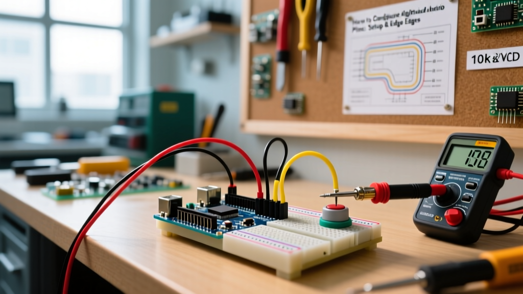
Setup A: Active-Low (Momentary Button)
- Connect one leg of the tactile switch to Arduino Digital Pin 2.
- Connect the opposite leg of the switch to Arduino GND.
- In
setup(), declarepinMode(2, INPUT_PULLUP);. - In
loop(), useif (digitalRead(2) == LOW) { // Button is pressed }.
Setup B: Active-High (Push-Pull Digital Sensor)
- Connect the sensor's digital OUT pin to Arduino Digital Pin 3.
- Connect a 10kΩ external resistor between Digital Pin 3 and GND (Pull-Down).
- In
setup(), declarepinMode(3, INPUT);. - In
loop(), useif (digitalRead(3) == HIGH) { // Sensor triggered }.
Signal Integrity: Debouncing and Noise Mitigation
Mechanical switches suffer from contact bounce. When the metal contacts close, they physically vibrate, causing the digitalRead() function to see dozens of rapid HIGH/LOW transitions over a 1ms to 10ms window. If you are counting button presses, a single press might register as five.
Comparison Matrix: Hardware vs Software Debouncing
| Method | Implementation | Pros | Cons |
|---|---|---|---|
| Hardware (RC Filter) | 10kΩ resistor + 100nF capacitor to GND, optionally fed through a 74HC14 Schmitt Trigger. | Zero CPU overhead; cleans signal before MCU sees it. | Requires extra PCB space and BOM cost; introduces slight propagation delay. |
| Hardware (Dedicated IC) | MAX6816 or MC14490 switch debouncers. | Perfect square wave output; handles ESD. | Overkill for simple hobby projects; expensive. |
| Software (Delay) | delay(50); after reading a state change. |
Easiest to write; no extra components. | Blocks the main loop; makes the MCU unresponsive to other tasks. |
| Software (State Machine) | Using the Bounce2 library via non-blocking timers. |
Highly reliable; keeps loop() unblocked; industry standard. | Requires installing a third-party library and understanding object instantiation. |
For 95% of modern maker projects, software debouncing using the Bounce2 library is the superior choice. It utilizes millis() to track state duration without halting the processor.
Microcontroller-Specific Edge Cases (2026 Update)
As the maker ecosystem has expanded beyond the classic 5V Arduino Uno, digitalRead() behavior has become heavily dependent on the specific silicon architecture. Refer to the Espressif GPIO API Reference for deep-dive ESP32 behaviors.
1. ESP32 Strapping Pin Conflicts
The ESP32 uses specific GPIO pins to determine boot modes (e.g., flash voltage, SPI boot). Pins like GPIO 0, GPIO 2, GPIO 12, and GPIO 15 are "strapping pins." If you configure GPIO 12 as INPUT_PULLUP or wire an external pull-up to it, the ESP32 may attempt to boot using 1.8V flash logic instead of 3.3V, resulting in a continuous boot loop. Avoid using strapping pins for digital inputs whenever possible.
2. Arduino Uno Analog Pins as Digital Inputs
On the ATmega328P, pins A0 through A5 can be used for digitalRead(). However, you can reference them either by their analog name (digitalRead(A0)) or their digital mapping (digitalRead(14)). Both work, but using the Ax nomenclature is highly recommended for code readability and cross-board compatibility (as the digital mapping shifts on the Arduino Mega 2560).
3. Execution Speed and Direct Port Manipulation
The standard Arduino digitalRead() reference abstracts the hardware registers, but this abstraction costs execution time. On a 16MHz ATmega328P, digitalRead() takes roughly 3 to 5 microseconds. If you are attempting to read a high-frequency digital signal (e.g., a 100kHz encoder pulse), digitalRead() will drop pulses. In these edge cases, you must bypass the Arduino API and read the AVR hardware registers directly (e.g., bool state = (PIND & (1 << PD2));), which executes in a single clock cycle (~62 nanoseconds).
Troubleshooting Checklist: When digitalRead() Fails
If your input is behaving erratically, run through this diagnostic checklist before rewriting your code:
- Phantom Triggers: Check for floating pins. Ensure
INPUT_PULLUPis declared or external pull-downs are soldered correctly. - Inverted Logic: Did you wire the switch to GND but forget to change your
ifstatement to look forLOW? - Multiple Triggers per Press: You are experiencing switch bounce. Implement the Bounce2 library or add a 100nF capacitor across the switch terminals.
- Pin Always Reads HIGH: If using an external pull-down, verify the resistor is actually connected to GND, not floating. Measure the voltage at the pin with a multimeter; it should read 0.00V when the switch is open.
- ESP32 Touch Pin Interference: Pins like GPIO 4, 13, 14, and 15 double as capacitive touch sensors. If you have initialized the touch peripheral elsewhere in your code, it may override the standard digital input buffer configuration.