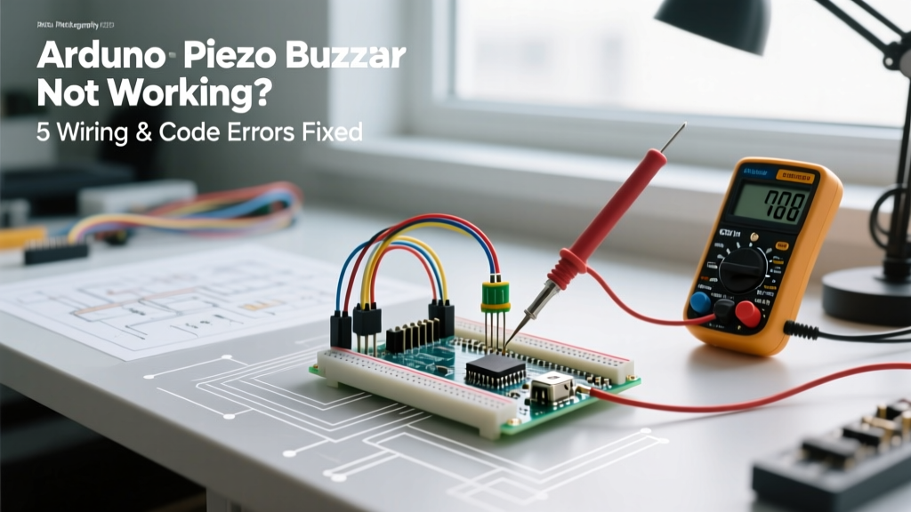

The Silence of the Maker: Diagnosing Piezo Buzzer Failures
There are few things more frustrating in embedded systems development than uploading a sketch, waiting for the expected auditory feedback, and being met with absolute silence. The Arduino piezo buzzer is a staple component in maker kits, alarm systems, and interactive DIY projects. Yet, despite its apparent simplicity, it remains one of the most frequently misunderstood components in the electronics hobbyist space.
When a piezo buzzer fails to sound, emits a faint click, or produces distorted static, the root cause almost always falls into one of two categories: a fundamental misunderstanding of the hardware's physical properties, or a software conflict within the Arduino IDE's timer architecture. In this comprehensive diagnostic guide, we will dissect the exact failure modes of piezo buzzers in 2026, moving beyond basic "check your wiring" advice to explore impedance mismatches, timer interrupts, and resonant frequency limitations.
The Fundamental Divide: Active vs. Passive Confusion
Before probing your breadboard with a multimeter, you must identify which type of buzzer you are holding. Treating a passive buzzer like an active one is the single most common reason for a silent circuit. Standard hobbyist modules like the KY-012 (Active) and KY-006 (Passive) look nearly identical but operate on entirely different electrical principles.
| Feature | Active Piezo Buzzer (e.g., KY-012) | Passive Piezo Buzzer (e.g., KY-006) |
|---|---|---|
| Internal Oscillator | Yes (Built-in driver circuit) | No (Bare piezoelectric ceramic) |
| Required Signal | Steady DC Voltage (HIGH) | AC Square Wave (PWM / tone()) |
| Typical Resonance | Fixed (usually 2.73 kHz) | Variable (Depends on input frequency) |
| Current Draw | ~30mA (Requires transistor for safety) | <5mA (Capacitive load, safe for GPIO) |
| Average Cost (2026) | $1.50 - $2.00 | $1.00 - $1.40 |
If you apply a constant HIGH digital signal to a passive buzzer, the ceramic disc will bend exactly once, producing a single, barely audible "click," and then remain entirely silent. Conversely, applying a high-frequency square wave to an active buzzer will often result in no sound, as the internal oscillator circuit expects a steady DC voltage to power its own internal waveform generation.
Hardware & Wiring Diagnostics
Error 1: PWM and Timer Conflicts (The Silent Killer)
If your passive buzzer is wired correctly but remains silent while other parts of your project (like an LED or motor) are functioning, you are likely experiencing a hardware timer collision. The official Arduino tone() function relies on the microcontroller's internal hardware timers to generate the required square wave without blocking the main loop.
On the standard Arduino Uno and Nano (ATmega328P architecture), the tone() function monopolizes Timer 2. This creates a critical conflict: Timer 2 also controls hardware PWM on Pins 3 and 11. If your sketch attempts to use analogWrite() on Pin 3 or 11 while simultaneously calling tone(), the PWM signal will fail, or the buzzer will behave erratically. On the Arduino Mega 2560, Timer 2 controls Pins 9 and 10. Always consult the specific timer-to-pin mapping for your microcontroller board before finalizing your breadboard layout.
Error 2: The Capacitive Spike and GPIO Stress
A common misconception is that because a passive piezo buzzer draws almost zero steady-state DC current, it is perfectly safe to drive directly from an ATmega328P GPIO pin. While a piezo element is essentially a capacitor (typically 2nF to 3nF for a 12mm disc), the instantaneous charging current ($I = C \frac{dv}{dt}$) during the rapid voltage transitions of a 4 kHz square wave can cause micro-spikes.
Expert Pro-Tip: While direct GPIO connection works for short testing phases, driving a piezo buzzer directly from a microcontroller pin for extended periods in a commercial or permanent installation can degrade the GPIO silicon over time. Always use a simple NPN transistor (like a 2N2222 or BC547) or a logic-level MOSFET to switch the buzzer, and place a 100Ω to 330Ω series resistor on the signal line to dampen high-frequency ringing and protect the pin.
Error 3: Missing Common Ground in Transistor Circuits
When you upgrade to a transistor-driven circuit to increase volume or use a 12V piezo siren, a frequent error is forgetting the common ground. If you are powering the buzzer from an external 9V or 12V battery pack, the ground rail of that external supply must be physically tied to the GND pin of the Arduino. Without this shared reference voltage, the Arduino's 5V logic signal has no baseline to trigger the transistor's base or gate, resulting in a completely dead circuit.
Software & Code Diagnostics
Error 4: Ignoring Resonant Frequency Limits
Piezo ceramics are highly resonant devices. A standard 12mm passive piezo diaphragm has a mechanical resonant frequency typically rated around 2.73 kHz ± 0.5 kHz. If you use the tone(pin, frequency) function and pass a value of 200 Hz (perhaps attempting to play a low bass note), the buzzer will not produce a low-pitched sound. Instead, the audio output will be infinitesimally quiet, or entirely imperceptible to the human ear, because the ceramic disc is being driven far outside its mechanical efficiency band.
To achieve maximum acoustic output, keep your tone() frequencies between 2,000 Hz and 4,000 Hz. If your project requires multi-octave musical melodies or low-frequency audio, a piezo buzzer is the wrong component. You must upgrade to an electromagnetic speaker or an I2S digital audio amplifier.
Error 5: The noTone() Omission and Blocking Delays
Another frequent coding error involves the improper use of delays and the failure to terminate the tone. If you call tone(8, 2000) without specifying a duration parameter, the buzzer will sound indefinitely until you explicitly call noTone(8).
Furthermore, beginners often use blocking delay() functions to time the buzzer, which halts all other microcontroller operations. As detailed in Adafruit's guide on multi-tasking the Arduino, relying on delay() prevents your board from reading sensors or updating displays while the buzzer is active. Instead, use the built-in duration parameter: tone(8, 2000, 500); (plays 2000Hz for 500 milliseconds) and manage timing via millis() for non-blocking execution.
The 5-Minute Diagnostic Flowchart
When your buzzer fails, follow this strict sequential checklist to isolate the fault in under five minutes:
- The Battery Test (Hardware Isolation): Disconnect the buzzer from the Arduino. Briefly touch the leads to a 3V coin cell or 5V USB line. If it's an active buzzer, it will emit a loud, continuous tone. If it's passive, you will only hear a single "click" upon connection and disconnection. This instantly confirms if the component is dead or alive.
- The Bare-Metal Sketch Test: Upload a blank sketch containing only
tone(8, 3000);in thesetup()loop. If it sounds, your hardware is fine, and the issue is a software timer conflict or logic error in your main codebase. - Pin Verification: Ensure you are not using Pins 3 or 11 on an Uno/Nano if your code also utilizes
analogWrite()or specific IR remote libraries (which also hijack Timer 2). - Multimeter Continuity Check: Measure the resistance across the buzzer pins. A passive piezo should show an open circuit (infinite resistance/OL) after a brief capacitive charging spike. An active buzzer will typically show a resistance between 10Ω and 50Ω due to its internal driver coil. If it reads 0Ω, the internal component is shorted and must be replaced.
When to Upgrade: Beyond the Piezo Buzzer
While the Arduino piezo buzzer is perfect for simple alerts, beeps, and error codes, the maker ecosystem in 2026 offers vastly superior alternatives for complex audio. If you find yourself constantly fighting the frequency limitations and tinny audio quality of piezo ceramics, it is time to transition to an I2S Audio Amplifier.
Modules like the MAX98357A (available for roughly $4.00 - $6.00 from reputable vendors) bypass the microcontroller's internal timers entirely. They accept digital audio streams via the I2S protocol, allowing you to play actual WAV files, polyphonic chimes, and high-fidelity voice prompts directly from an SD card or flash memory. For projects requiring professional-grade auditory feedback, abandoning the piezo element in favor of a digital audio pipeline is the ultimate solution.
By understanding the electromechanical realities of piezo ceramics and the architectural constraints of the ATmega microcontrollers, you can eliminate buzzer-related bugs permanently. Always verify your component type, respect the hardware timers, and design your circuits with long-term GPIO health in mind. For more advanced sensor integration and audio techniques, consult the SparkFun Experiment Guides and official hardware documentation.