
What is the Arduino NAO Concept?
The SoftBank NAO robot has long been the gold standard in educational and research-based humanoid robotics. Originally developed by Aldebaran Robotics, the NAO platform features 25 degrees of freedom (DoF), advanced sonar arrays, and a sophisticated Linux-based operating system. However, with institutional pricing hovering around $12,500 in 2026, the platform remains out of reach for most independent makers, hobbyists, and underfunded university labs.
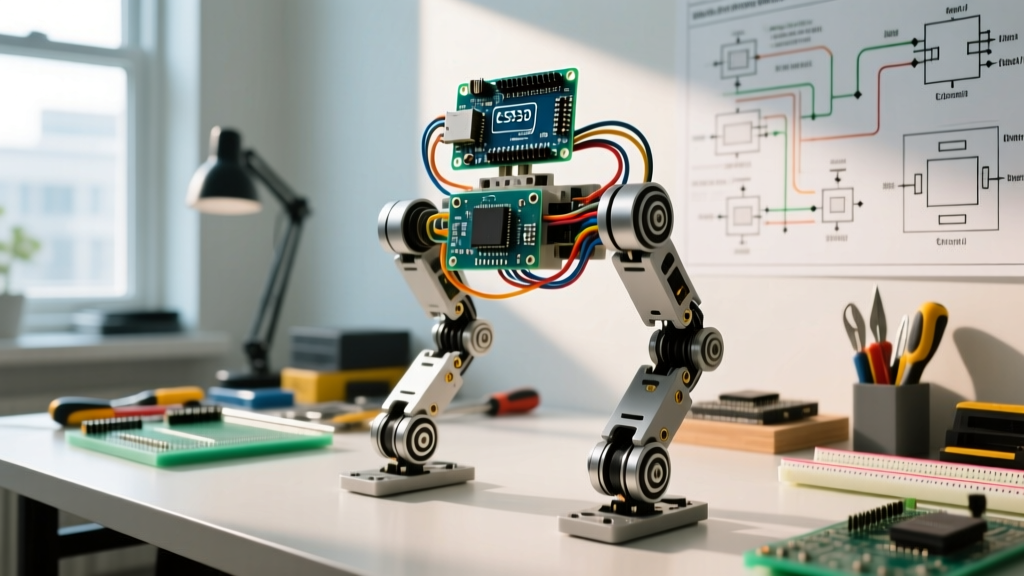
This economic barrier birthed the Arduino NAO concept: a grassroots engineering movement focused on designing, scaling, and programming low-cost, Arduino-controlled bipedal robots that mimic the kinematic architecture of the commercial NAO. Rather than attempting a 1:1 replica, the Arduino NAO concept distills the core principles of bipedal locomotion—dynamic balancing, inverse kinematics (IK), and multi-servo coordination—into an accessible, open-source hardware stack.
Building an Arduino-based humanoid is not merely about assembling parts; it is a rigorous exercise in embedded systems engineering, power management, and control theory. This guide deconstructs the architecture required to bring an Arduino NAO clone to life.
Commercial NAO vs. Arduino DIY Clone: A Technical Comparison
Understanding the trade-offs between the commercial platform and a DIY approach is critical before sourcing components. Below is a structural comparison of the two paradigms.
| Feature | SoftBank NAO V6 (Commercial) | Arduino NAO Clone (DIY) |
|---|---|---|
| Cost | ~$12,500 USD | $250 - $450 USD |
| Primary MCU/CPU | Intel Atom E3845 (Quad-core) | Arduino Mega 2560 or Teensy 4.1 |
| Degrees of Freedom | 25 DoF | 12 to 18 DoF (typically) |
| Actuators | Custom Brushless / High-end Servos | DS3218MG or MG996R Digital Servos |
| OS / Framework | NAOqi (Custom Linux) | Bare-metal C++ / ROS via Serial |
| Balance Mechanism | Proprietary IMU + Ankle Force Sensors | MPU6050 IMU + PID Feedback Loop |
Core Architecture: Brains, Brawn, and Balance
Translating the Arduino NAO concept from a 3D model to a walking physical entity requires strict attention to three subsystems: the microcontroller, the actuators, and the power distribution network.
1. Microcontroller Selection: The Brains
The Arduino Mega 2560 is the traditional starting point for humanoid clones due to its 54 digital I/O pins and 15 PWM channels. However, calculating Inverse Kinematics (IK) in real-time requires heavy floating-point math. The ATmega2560 chip operates at 16 MHz and lacks a hardware floating-point unit (FPU), meaning complex trigonometric calculations for joint angles can introduce latency, resulting in a sluggish or stuttering walking gait.
The 2026 Upgrade Path: Serious builders now bypass the Mega in favor of the Teensy 4.1. Clocking in at 600 MHz with an ARM Cortex-M7 core and a dedicated FPU, the Teensy 4.1 can execute IK matrices and PID loops at 500 Hz without breaking a sweat, all while maintaining compatibility with the Arduino IDE.
2. Actuator Sizing and Degrees of Freedom
A functional bipedal robot requires a minimum of 12 DoF to achieve basic omnidirectional walking (3 DoF per leg: hip roll, hip pitch, knee pitch). To replicate the NAO's fluid arm movements, makers typically add 4 to 6 DoF for the shoulders and elbows.
- Hips and Knees (High Torque): Use DS3218MG digital servos. These provide 20kg/cm of torque at 6V, feature metal gears, and cost roughly $22 each. They are essential for supporting the robot's chassis weight during the single-leg support phase of the gait cycle.
- Ankles and Arms (Medium Torque): MG996R servos (13kg/cm torque, ~$12 each) are sufficient for ankle pitch/roll and arm articulation, reducing overall weight and cost.
- End Effectors (Low Torque): MG90S micro servos can be used for hand grippers or head panning.
3. Power Distribution and Brownout Prevention
The most common point of failure in Arduino NAO projects is inadequate power routing. When a 14-servo biped transitions from a crouch to a stand, multiple high-torque servos may draw stall current simultaneously. A single DS3218 can pull up to 2.5A under stall conditions. If 12 servos spike concurrently, the current draw can exceed 20A.
The Solution: Never power the servo bus from the Arduino's onboard 5V regulator. Instead, use a 3S LiPo battery (11.1V, 2200mAh, 40C discharge rate) paired with a high-amperage synchronous buck converter (such as a Drok 20A step-down module). Set the buck converter output precisely to 6.0V. Run a dedicated, heavy-gauge (14 AWG) silicone wire harness directly from the buck converter to a custom servo power bus board. The Arduino and the servo bus must share a common ground, but their positive voltage rails must remain strictly isolated.
Expert Insight: To eliminate voltage ripple caused by rapid servo current spikes, solder a bank of three 4700µF 10V low-ESR electrolytic capacitors directly across the main 6V servo bus terminals. This acts as a localized energy reservoir, preventing the microcontroller from browning out during high-load kinematic shifts.
Sensory Feedback and Inverse Kinematics
A robot that simply moves its servos through pre-recorded trajectories will fall over the moment it encounters a sloped surface or an external push. True bipedal locomotion requires closed-loop feedback.
Integrating the MPU6050 IMU
The MPU6050 6-axis Inertial Measurement Unit (IMU) is the vestibular system of the Arduino NAO. Mounted precisely at the robot's center of mass (usually the pelvic chassis), it provides real-time pitch and roll data. By utilizing the MPU6050's onboard Digital Motion Processor (DMP), the Arduino can offload sensor fusion calculations, retrieving clean quaternion data via the I2C bus at 100 Hz.
The PID Balance Loop
To maintain balance, the IMU data is fed into a Proportional-Integral-Derivative (PID) controller. If the robot begins to pitch forward, the PID algorithm calculates the necessary error correction and commands the ankle pitch servos to dorsiflex (tilt upward) while simultaneously adjusting the hip pitch to keep the torso upright. Tuning the PID gains (Kp, Ki, Kd) is highly specific to the robot's exact mass distribution; a typical starting point for a 1.5kg Arduino biped is Kp = 2.5, Ki = 0.05, Kd = 1.2.
Step-by-Step Assembly and Boot Framework
Executing a safe boot sequence is critical to prevent the robot from violently snapping its joints upon power-up, which can strip servo gears or shatter 3D-printed PLA brackets.
- Physical Restraint: Place the robot in a calibration stand or suspension rig so its feet are off the ground and joints are at their mechanical zero-points.
- Logic Power On: Connect the USB data cable or auxiliary 5V logic supply to the Arduino/Teensy. The MCU boots, initializes the I2C bus, and reads the MPU6050 calibration offsets.
- PWM Driver Initialization: The MCU sends initialization commands to the PCA9685 I2C servo driver board, setting the PWM frequency to 50Hz and ensuring all channels are set to a neutral 1500µs pulse width.
- Main Power On: Connect the 3S LiPo battery to the buck converter. The 6V servo bus energizes. Because the PCA9685 is already holding the neutral signal, the servos engage softly without jittering.
- Software Compliance Engage: The main loop begins, slowly ramping up the PID loop integral term to avoid sudden corrective jerks, and transitions the robot into the 'ready' stance.
Common Failure Modes and Edge Cases
Even with perfect hardware, software and environmental edge cases will plague early testing phases. Anticipating these issues separates novices from advanced robotics engineers.
- I2C Clock Stretching Crashes: The MPU6050 is notorious for occasionally holding the I2C clock line low if its internal FIFO buffer overflows, freezing the Arduino. Fix: Implement a hardware watchdog timer and use pull-up resistors (4.7kΩ) on the SDA/SCL lines. Better yet, use an I2C multiplexer or isolate the IMU on a secondary software I2C bus.
- Servo Jitter under Load: If servos chatter audibly when holding a static pose, the issue is rarely the servo itself. It is usually noisy power or software interrupt conflicts. Fix: Never use the Arduino's
Servo.hlibrary for humanoid robots, as timer interrupts cause PWM jitter. Always use a dedicated hardware PWM driver like the PCA9685. - Kinematic Singularities: When the robot's leg approaches full extension (knee perfectly straight), the IK math can divide by zero or demand infinite joint velocity, causing the MCU to crash or the servo to snap. Fix: Implement software joint limits that prevent the knee pitch from reaching exactly 180 degrees, capping it at 175 degrees to maintain a mathematical safety margin.
Conclusion
The Arduino NAO concept represents the ultimate intersection of mechanical design, embedded programming, and control theory. While it lacks the polished exterior and proprietary AI of its $12,000 commercial counterpart, an Arduino-based bipedal clone offers something far more valuable to the maker: complete transparency. By mastering the power distribution, selecting high-torque digital servos, and implementing robust inverse kinematics, builders can create a dynamic, walking robot that serves as a profound educational tool and a testament to open-source engineering.