
The Anatomy of an Arduino Modbus RTU Failure
Integrating an Arduino into an industrial automation setup using Modbus RTU over RS485 is a rite of passage for advanced makers and IoT engineers. Whether you are polling a PZEM-016 energy meter, controlling a VFD (Variable Frequency Drive), or reading registers from a PLC, the protocol is robust. However, the physical and data-link layers are notoriously unforgiving. When your serial monitor spits out E2 (Timeout) or E1 (Illegal Function/CRC) errors, the root cause is rarely the Modbus protocol itself. Instead, it usually stems from transceiver voltage mismatches, missing bias resistors, or microsecond-level DE/RE pin timing faults.
This guide bypasses generic advice and dives deep into the exact hardware configurations, timing mathematics, and library-specific quirks required to stabilize your Arduino Modbus network in 2026.
Physical Layer: RS485 Transceiver & Wiring Faults
The most common point of failure in Arduino Modbus implementations is the physical RS485 transceiver module. The Arduino ecosystem is flooded with cheap MAX485 breakout boards, but these are fundamentally mismatched for modern 3.3V microcontrollers.
Transceiver Selection: MAX485 vs. SP3485
- MAX485 (5V Logic): If you are using a 5V Arduino Uno or Mega, the classic MAX485 will work. However, if you connect this to a 3.3V ESP32, Arduino Portenta, or Teensy, the 5V TX/RX signals will fry your MCU's GPIO pins, or the 3.3V logic won't trigger the MAX485's DI/RE thresholds.
- SP3485 (3.3V Logic): For 3.3V boards, you must use an SP3485-based module. It operates reliably at 3.3V and supports baud rates up to 10 Mbps.
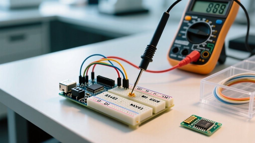
- Isolated Modules (e.g., HW-519): In industrial environments with heavy inductive loads (like motors and contactors), ground loops will destroy your Arduino. As of 2026, isolated RS485 modules cost between $3.50 and $5.00 and feature built-in optocouplers and isolated DC-DC converters. Always use isolated modules when connecting an Arduino to mains-powered PLCs or VFDs.
Wiring, Termination, and Biasing
According to the Modbus Organization Specification, the physical layer requires strict adherence to differential signaling rules. A floating RS485 bus will pick up electromagnetic interference (EMI), resulting in phantom bytes that corrupt the CRC checksum.
Pro-Tip: Many Chinese-manufactured RS485 modules label the terminals asD+andD-. In 90% of cases,D+maps to RS485A(Non-Inverting) andD-maps toB(Inverting). However, always verify with the target device's manual, as some manufacturers swap this convention.
The 120/390 Ohm Rule:
- Termination: Place a 120Ω resistor across the A and B lines at the first and last physical nodes on the bus. If your Arduino is in the middle of the daisy chain, do not enable its onboard termination jumper.
- Biasing (Failsafe): When the bus is idle, the voltage differential between A and B is zero, which the receiver interprets as random noise. To force an idle (HIGH) state, add a 390Ω pull-up resistor from
AtoVCCand a 390Ω pull-down resistor fromBtoGNDat the master node (your Arduino).
Data Link Layer: Baud Rates and the 3.5 Character Rule
Modbus RTU does not use a start/stop byte to frame messages; it relies on a silent interval of at least 3.5 character times to determine the end of a frame. If your Arduino sends a command but fails to respect this timing, the slave device will treat the response as a continuation of the previous message, triggering a CRC error.
Calculating the 3.5 Character Delay
A standard Modbus character consists of 11 bits (1 start, 8 data, 1 parity, 1 stop). The timing depends entirely on your baud rate:
- At 9600 Baud: 11 bits / 9600 bps = 1.145 ms per character. The 3.5 char gap requires a silence of ~4.0 ms.
- At 19200 Baud: The gap shrinks to ~2.0 ms.
- At 115200 Baud: The gap is ~0.33 ms.
Critical Warning: Do not attempt to run Modbus RTU at 115200 baud using SoftwareSerial on an AVR-based Arduino (Uno/Nano). The software interrupt latency will mangle the 3.5 character gap, resulting in 100% packet loss. Always use hardware serial (Serial1, Serial2) for baud rates above 38400.
Software Layer: DE/RE Pin Timing & Library Selection
RS485 is half-duplex. The Arduino must toggle the Driver Enable (DE) and Receiver Enable (RE) pins to switch between transmitting and listening. If you switch to RX mode too early, you truncate your own message. If you switch too late, you miss the slave's response.
Configuring ModbusMaster Callbacks
The Doc Walker's ModbusMaster GitHub repository remains the gold standard for AVR and ESP-based RTU communication. To handle the DE/RE pin toggling flawlessly, you must use the preTransmission and postTransmission callbacks rather than simple delay() functions in your main loop.
// Define your DE/RE control pin
const uint8_t DE_RE_PIN = 8;

void preTransmission() {
  digitalWrite(DE_RE_PIN, HIGH); // Enable Driver (TX)
  // Allow hardware capacitance to charge
  delayMicroseconds(50);
}

void postTransmission() {
  // Wait for the last byte to physically leave the shift register
  // For 9600 baud, 1 byte takes ~1.14ms. We wait 2ms to be safe.
  delay(2);
  digitalWrite(DE_RE_PIN, LOW);  // Enable Receiver (RX)
}
If you are using the official Arduino Modbus library documentation (which wraps libmodbus and is heavier but supports TCP as well), the hardware serial flow control is often handled automatically by the underlying C library, provided you are using an MKR or Portenta board with native RS485 shields.
Diagnostic Matrix: Decoding ModbusMaster Error Codes
When node.readHoldingRegisters() fails, it returns a hex code. Use this matrix to pinpoint the exact failure domain.
| Error Code | Hex Value | Meaning | Root Cause & Fix |
|---|---|---|---|
| Success | 0x00 |
Transaction successful | No action required. |
| Illegal Function | 0x01 |
Slave doesn't support the requested function code | You sent 0x03 (Read Holding) but the register is an Input Register (0x04). Check the slave's manual. |
| Illegal Data Address | 0x02 |
Register address does not exist | Off-by-one error. Some PLCs use 0-based addressing in code but 1-based in documentation. Subtract 1 from your address. |
| Response Timed Out | 0xE2 |
Arduino didn't receive a reply within the timeout window | Check A/B wiring, verify slave ID, ensure DE/RE pin is dropping LOW to allow RX, or increase the setTimeout() value. |
| Invalid CRC | 0xE1 |
Checksum mismatch on received packet | EMI corruption on the bus. Add 120Ω termination resistors, use shielded twisted-pair (STP) cable, or lower the baud rate to 9600. |
Advanced Debugging: Logic Analyzers and Oscilloscopes
If you have verified the wiring, confirmed the baud rate, and implemented the DE/RE callbacks, but you are still facing 0xE2 Timeouts, it is time to look at the physical waveforms.
Using a Logic Analyzer on RO and DI
Connect a cheap 8-channel logic analyzer (like a Saleae clone) to the RO (Receive Out) and DI (Data In) pins between the Arduino and the MAX485 module. Trigger on the falling edge of the DE/RE pin.
- What to look for: You should see the Arduino transmit the exact Modbus frame on
DI. Immediately after the DE/RE pin goes LOW, you should see the slave's response onRO. - The "Echo" Problem: If you see your own transmitted message bouncing back on
ROwhile DE is HIGH, your module's RE pin is not properly tied to the DE pin, or the module is defective. Ensure DE and RE are physically jumpered together on the breakout board.
Oscilloscope Differential Probing
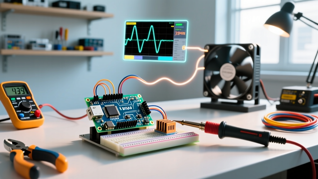
To diagnose 0xE1 (Invalid CRC) errors caused by noise, use an oscilloscope to probe the A and B lines at the slave device's terminals. Set the math function to Channel A - Channel B. The differential signal should show clean, sharp square waves with a minimum amplitude of 1.5V. If the signal looks like a rounded, noisy sine wave, your cable capacitance is too high. Reduce the baud rate, or switch to a higher-quality RS485 transceiver with integrated slew-rate limiting to reduce high-frequency ringing.