
The Hidden Culprit Behind Arduino Resets: Power Instability
When an Arduino sketch behaves erratically—randomly resetting, locking up I2C buses, or returning chaotic analog-to-digital (ADC) readings—most makers immediately suspect flawed code or a defective microcontroller. However, in professional embedded systems diagnostics, up to 70% of these 'ghost' errors trace back to a single root cause: improper power delivery. Understanding exactly how to power Arduino hardware is not just about plugging in a cable; it requires a deep understanding of voltage regulation, transient current demands, and brownout thresholds.
This diagnostic guide moves beyond basic wiring diagrams. We will dissect the specific failure modes of Arduino power architectures, from the legacy ATmega328P linear regulators to the modern USB-C Power Delivery (PD) negotiation circuits found on 2026-era boards like the Arduino Uno R4 Minima and Nano ESP32.
4 Ways to Power an Arduino (And Where They Fail)
Every Arduino board features multiple power ingress points, each with distinct electrical characteristics and specific failure modes. Below is a diagnostic matrix comparing the primary power methods.
| Power Method | Input Voltage Range | Max Safe Current | Primary Diagnostic Failure Mode |
|---|---|---|---|
| USB (Type-B / Type-C) | 4.75V - 5.25V | 500mA (USB 2.0) / 900mA (USB 3.0) | Polyfuse (PTC) thermal trip; USB-C CC-line negotiation failure. |
| Barrel Jack (DC) | 7V - 12V (Recommended) | ~800mA (Thermal Limited) | NCP1117 linear regulator thermal shutdown due to high voltage dropout. |
| 5V Pin (Direct) | 4.8V - 5.2V (Strict) | Limited by external supply | Overvoltage transients instantly destroying the MCU logic gates. |
| Vin Pin | 7V - 12V | Same as Barrel Jack | Reverse polarity damage (missing protection diodes on clone boards). |
Diagnosing the 'Random Reset' Error: Brownout Detection (BOD)
If your Arduino resets precisely when a high-current peripheral (like a servo motor, relay module, or GSM shield) activates, you are experiencing a transient voltage droop triggering the microcontroller's Brown-out Detection (BOD) circuit.
Understanding the ATmega328P BOD Thresholds
According to the Microchip ATmega328P Datasheet, the BOD monitors the VCC pin. If the voltage drops below the programmed threshold (typically 2.7V or 4.3V, depending on the fuse bits set during factory flashing), the MCU forces a hardware reset to prevent the CPU from executing corrupted instructions out of flash memory.
The Diagnostic Edge Case: What happens if the voltage droops to 2.9V? It is above the 2.7V BOD threshold, meaning the MCU will not reset. However, 2.9V is below the safe operating voltage for a 16MHz crystal oscillator. The clock signal degrades, the program counter jumps to a random memory address, and the board 'locks up' without resetting.
Expert Diagnostic Rule: If your Arduino freezes and requires a manual physical reset, suspect a marginal voltage droop that bypassed the BOD threshold but crashed the oscillator. If it resets itself automatically, the BOD successfully caught a severe voltage drop.
Step-by-Step: Capturing Transient Droops
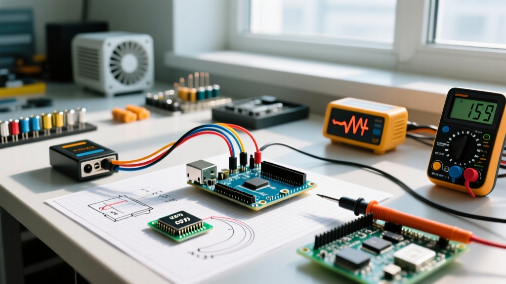
A standard digital multimeter (DMM) sampling at 3Hz is useless for catching a 50-millisecond servo startup spike. To properly diagnose this:
- Use an Oscilloscope: Set your scope to DC coupling, 1V/div, and enable 'Single Sequence' trigger mode on a falling edge at 4.5V.
- Probe the 5V Pin: Attach the probe directly to the Arduino's 5V output pin, not the USB cable.
- Trigger the Load: Run your sketch. When the peripheral activates, the scope will capture the exact microsecond voltage dip.
- The Fix: Solder a 470µF low-ESR electrolytic capacitor and a 100nF ceramic capacitor in parallel across the 5V and GND rails near the peripheral's power ingress.
Troubleshooting Voltage Regulator Overheating (The NCP1117 Limit)
Legacy boards like the Arduino Uno R3 utilize an NCP1117ST50T3G linear regulator to step down voltage from the Barrel Jack or Vin pin to 5V. Linear regulators do not magically convert excess voltage into current; they burn it off as heat. This is the most common reason makers ask how to power Arduino projects safely when using 9V or 12V wall adapters.
The Thermal Shutdown Calculation
The ON Semiconductor NCP1117 Datasheet specifies a thermal shutdown threshold of approximately 150°C. To diagnose if your board is thermally throttling, calculate the power dissipation ($P_d$):
Formula: $P_d = (V_{in} - V_{out}) \times I_{load}$
Real-World Scenario: You power an Uno R3 via a 12V adapter and connect a motor shield drawing 300mA from the 5V rail.
- $V_{in} = 12V$
- $V_{out} = 5V$
- $I_{load} = 0.3A$
- $P_d = (12 - 5) \times 0.3 = 2.1 Watts$
The SOT-223 package has a junction-to-ambient thermal resistance ($\theta_{JA}$) of roughly 100°C/W. A 2.1W dissipation results in a temperature rise of 210°C above ambient. The regulator will hit 150°C and shut down in seconds, cutting power to the MCU. When it cools, it restarts, creating an endless boot-loop.
The Fix: If your project requires more than 150mA of 5V current, never use the Barrel Jack with a 12V supply. Either drop the input voltage to 7.5V, or bypass the onboard regulator entirely by feeding a clean, regulated 5V directly into the '5V' pin using an external buck converter (like an LM2596 module).
USB-C Power Delivery Errors on Modern Boards
Moving into 2026, the ecosystem has largely adopted USB-C for boards like the Arduino Uno R4 WiFi, Nano ESP32, and various RP2040-based MCUs. While USB-C offers higher current limits, it introduces a new layer of diagnostic complexity: CC (Configuration Channel) line negotiation.
If you plug a modern Arduino into a high-wattage laptop charger and the board fails to power on, or the IDE throws a 'USB Enumeration Failed' error, the issue is often the cable, not the board.
- Charge-Only Cables: These lack the internal CC data lines. The Arduino's USB-C controller cannot negotiate a power role, and the host defaults to 0V or 500mA, which is insufficient to boot the ESP32-S3 radio stack.
- E-Marker Chip Conflicts: Some cheap USB-C cables have improperly programmed E-marker chips that misreport their current capabilities, causing the Arduino's power management IC (PMIC) to reject the connection for safety.
Diagnostic Step: Always keep a certified, data-capable USB-C 3.1 Gen 2 cable (rated for 100W/5A) in your toolkit. If a modern board fails to enumerate on USB-C, swap the cable before suspecting a dead bootloader or corrupted USB controller.
Expert Diagnostic Checklist for Arduino Power Failures
When a board refuses to boot or behaves erratically, run through this hardware-level checklist before reflashing the firmware.
- Verify the PTC Resettable Fuse (F1): On the Uno R3, F1 is a 500mA polyfuse located near the USB port. If you shorted a peripheral, F1 heats up and goes high-resistance (sometimes >50 ohms). Measure the voltage drop across F1 while connected to USB. A drop greater than 0.3V indicates a tripped or degraded fuse.
- Inspect the Schottky Diode (D1): The MBR0520 diode prevents back-feeding voltage from the Barrel Jack into the USB port. If your PC's USB hub disconnects when you plug in the DC barrel jack, D1 has failed short.
- Measure the 3.3V Rail: Many sensors require 3.3V. The onboard 3.3V regulator (often an LP2985 or similar) is usually limited to 50mA-150mA. Overloading this rail causes brownouts specifically on the sensor bus, leading to I2C 'NACK' errors while the main MCU remains perfectly stable.
- Check Ground Loops: When powering an Arduino via a bench supply while simultaneously connecting it to a PC via USB for serial debugging, slight differences in ground potentials can cause data corruption on the TX/RX lines. Use an isolated USB hub or a digital isolator (like the ADuM1201) for serial debugging in mixed-power environments.
Summary
Mastering how to power Arduino systems requires shifting your mindset from simple connectivity to active power management. By calculating thermal limits, respecting BOD thresholds, and understanding modern USB-C negotiation, you can eliminate the vast majority of hardware-level errors that plague embedded projects. For further reading on official power architectures, refer to the Arduino Official Powering Guide to ensure your specific board variant is operating within its engineered safe operating area (SOA).