
The Bottleneck in Standard Joystick Workflows
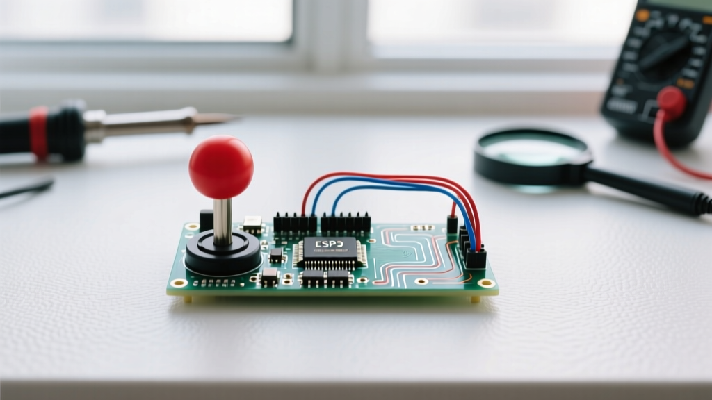
Most makers treat the arduino joystick circuit diagram as an afterthought, simply jumpering VCC, GND, and the analog pins directly to a breadboard. While this works for blinking LEDs or basic menu navigation, it completely falls apart in precision applications like robotic arm teleoperation, camera gimbals, or PID-controlled balancing rovers. The result? Jittery ADC readings, axis cross-talk, and mechanical switch bounce that introduces micro-stutters into your control loop.
In 2026, with the widespread adoption of high-polling-rate microcontrollers like the ESP32-S3 and Raspberry Pi Pico 2, the hardware bottleneck has shifted. Your MCU can sample thousands of times per second, but if your physical circuit is injecting electromagnetic interference (EMI) or suffering from impedance mismatches, your software will spend valuable CPU cycles filtering out garbage data. This guide focuses on workflow optimization: designing a robust, production-ready joystick circuit that eliminates noise at the hardware level, allowing your firmware to run lean and fast.
Component Selection: Potentiometer vs. Hall-Effect
Before drawing your schematic, you must select the right transducer for your latency and lifespan requirements. The market has shifted significantly over the last few years, making magnetic sensors far more accessible.
| Module Type | Typical Cost (2026) | Wiper Impedance | Jitter Profile | Best Use Case |
|---|---|---|---|---|
| KY-023 (Carbon Pot) | $1.20 - $1.80 | 10kΩ | High (±15 ADC steps) | Prototyping, basic UI menus |
| PS2 Analog (Carbon Pot) | $2.50 - $3.50 | 10kΩ | Moderate (±8 ADC steps) | RC transmitters, gaming |
| Alps RKJXT1F42001 (Hall-Effect) | $6.50 - $8.50 | N/A (Magnetic) | Ultra-Low (±1 ADC step) | Industrial robotics, drones, gimbals |
Workflow Tip: If you are building a device intended for more than 10,000 actuation cycles, skip the carbon potentiometers. As detailed in Adafruit's comprehensive joystick guide, carbon tracks physically degrade, creating dead zones and resistance spikes that no amount of software filtering can reliably fix.
The Optimized Arduino Joystick Circuit Diagram
To achieve zero-latency, jitter-free input, we must optimize the analog front-end. The standard wiring relies entirely on the microcontroller's internal pull-up resistors and raw ADC sampling. Our optimized workflow introduces passive hardware filtering and dedicated switch debouncing.
Step 1: Power and Ground Routing
Never share the joystick's ground return path with high-current components like motor drivers or relays. Route a dedicated ground wire from the joystick module directly to the microcontroller's analog ground (AGND) pin if available, or the primary GND star point. This prevents ground bounce from shifting your 0V reference, which manifests as random spikes in your joystick readings.
Step 2: The Hardware Low-Pass Filter (RC Decoupling)
The most critical addition to your arduino joystick circuit diagram is the implementation of an RC (Resistor-Capacitor) low-pass filter on the analog output lines. A standard joystick potentiometer outputs a high-impedance signal that acts like an antenna for high-frequency EMI from nearby switching regulators or PWM motor signals.
- Capacitor Selection: Solder a 100nF (0.1µF) ceramic capacitor between the VRx (X-axis) analog pin and GND. Repeat for VRy (Y-axis).
- The Math: The joystick's internal potentiometer is typically 10kΩ. At the midpoint (5kΩ), combined with a 100nF capacitor, the cutoff frequency ($f_c$) is approximately 318 Hz. Since human thumb movements rarely exceed 10 Hz, this filter physically blocks all high-frequency noise without introducing perceptible input lag.
Step 3: Switch Pin Optimization
The integrated push-button (SW pin) is notorious for mechanical bounce. While software debouncing works, it consumes CPU cycles and introduces a 20-50ms delay. Optimize the hardware by placing a 10kΩ external pull-up resistor to VCC and a 100nF capacitor between the SW pin and GND. This creates a hardware debounce circuit, allowing you to trigger instantaneous hardware interrupts in your code without false triggers.
Software Workflow: Bypassing analogRead() Limitations
Even with a perfect circuit diagram, the default Arduino `analogRead()` function is a workflow bottleneck. On an ATmega328P (Uno/Nano), the default ADC prescaler is 128, resulting in an ADC clock of 125kHz. A single conversion takes 13 ADC cycles, meaning one `analogRead()` takes roughly 104 microseconds. Reading both X and Y axes takes over 200 microseconds.
Manipulating the ADC Prescaler
For joystick inputs, 10-bit resolution (1024 steps) is often overkill; 8-bit resolution is usually sufficient for mapping to servos or motor speeds. By altering the ADCSRA register, you can speed up the sampling rate drastically. According to the official Microchip ATmega328P datasheet, changing the prescaler to 32 yields an ADC clock of 500kHz, reducing conversion time to roughly 26 microseconds per axis.
Workflow Optimization Code Snippet:
ADCSRA = (ADCSRA & 0xF8) | 0x05; // Sets prescaler to 32
This single line in yoursetup()function quadruples your analog sampling speed, freeing up the main loop for complex kinematics or wireless transmission tasks.
Solving Axis Cross-Talk (The Ghosting Phenomenon)
A common edge case in dual-axis joystick circuits is "ghosting," where moving the X-axis slightly alters the Y-axis reading. This is not a flaw in your joystick; it is a limitation of the microcontroller's internal ADC multiplexer.
Inside the MCU, a single sample-and-hold capacitor (roughly 14pF) is shared across all analog pins. When the multiplexer switches from A0 (X) to A1 (Y), the capacitor retains a residual charge from the previous reading. If the joystick's potentiometer impedance is too high, it cannot charge or discharge this internal capacitor fast enough before the conversion completes.
The Double-Read Framework
To eliminate cross-talk without adding external op-amp buffers, implement the "double-read" workflow in your firmware:
- Set the multiplexer to the target pin.
- Perform a "dummy"
analogRead()and discard the value. This gives the internal capacitor time to settle to the new voltage. - Perform the second
analogRead()and use this value for your logic.
This software technique, combined with the 100nF hardware decoupling capacitors mentioned earlier, guarantees complete axis isolation.
Calibration and Deadzone Mapping
No joystick is perfectly centered. A raw reading of 512 is rare; most rest between 505 and 520. To optimize your control workflow, implement a dynamic deadzone mapping function rather than hardcoding values.
Use a struct to store your calibration data:
- Center Offset: Calculated on boot by averaging 100 samples while the user is instructed not to touch the stick.
- Deadzone Threshold: Typically set to ±15 ADC steps from the center offset to prevent motor creep when the stick is released.
- Exponential Scaling: Map the outer 70% of the throw to a cubic curve for fine motor control, reserving the edges for maximum velocity.
For handling the push-button without blocking delays, utilize the state-change detection workflow outlined in the Arduino basic debouncing documentation, relying on millis() rather than delay() to maintain a non-blocking main loop.
Real-World Failure Modes and Debugging
Even with an optimized arduino joystick circuit diagram, field deployments introduce new variables. Keep this troubleshooting matrix handy for your debugging workflow:
| Symptom | Probable Cause | Optimized Solution |
|---|---|---|
| Readings max out at 1023 randomly | Loose GND connection or ground loop | Solder GND directly; avoid breadboard clips for ground returns. |
| Values drift slowly over 10 minutes | Thermal drift in carbon potentiometer | Upgrade to a Hall-effect magnetic sensor module. |
| Push-button triggers multiple events | EMI inducing voltage spikes on long wires | Add a 100nF ceramic cap directly across the switch terminals. |
| ADC values are stuck at 0 or 1023 | Impedance mismatch or damaged ADC pin | Verify wiring; add a 1kΩ series resistor to protect the MCU pin. |
Conclusion: Hardware First, Software Second
Optimizing your workflow means solving problems at the lowest possible layer of the stack. By upgrading your arduino joystick circuit diagram to include passive RC filtering, dedicated grounding, and hardware debouncing, you eliminate the need for heavy, latency-inducing software filters. Combined with ADC prescaler manipulation and double-read multiplexing, your microcontroller will process human input with zero perceptible lag, resulting in a responsive, professional-grade control interface.