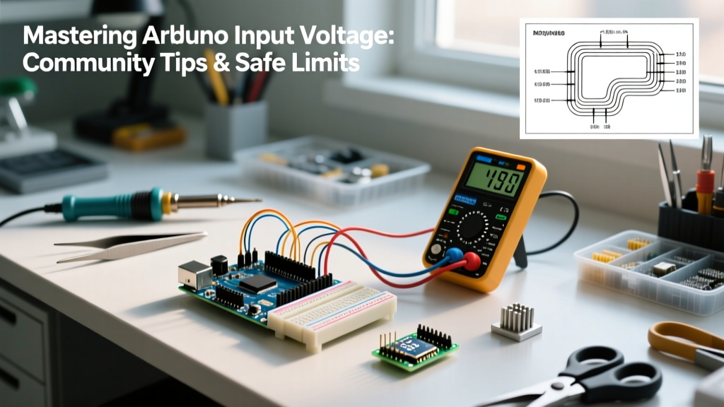

The "Magic Smoke" Problem: Why Arduino Input Voltage Matters
Every maker has a story about the first time they accidentally fried a microcontroller. In the Arduino Uno Rev3 Official Documentation, the recommended operating parameters are clearly stated, yet forum after forum is filled with posts about melted headers and dead voltage regulators. The culprit? Misunderstanding Arduino input voltage limits and the hidden thermal bottlenecks of onboard linear regulators.
In this community resource roundup, we have synthesized years of hard-won advice from Reddit’s r/arduino, the EEVblog forums, and StackExchange to give you a definitive, expert-level guide to powering your projects safely in 2026. We will move beyond the basic "7-12V" sticker on the box and dive into thermal dissipation math, edge-case failure modes, and modern power topology alternatives.
Hard Specs: Board-by-Board Voltage Matrix
Not all boards are created equal. The silicon and regulators used across the Arduino ecosystem dictate your safe operating area (SOA). Below is a comparison matrix of the most popular development boards.
| Board Model | Recommended Vin | Absolute Max Vin | Onboard Regulator | 5V Pin Max Draw |
|---|---|---|---|---|
| Arduino Uno R3 | 7V - 12V | 20V | NCP1117ST50T3G (SOT-223) | ~800mA (Thermal limited) |
| Arduino Nano (Clone) | 7V - 9V | 12V | AMS1117-5.0 (SOT-223) | ~500mA (Thermal limited) |
| Arduino Mega 2560 | 7V - 12V | 20V | NCP1117ST50T3G | ~800mA (Thermal limited) |
| ESP32 DevKitC | 5V (via USB/Micro) | 6V (Vin pin) | AMS1117-3.3 | ~500mA (3.3V rail) |
Note: The "Absolute Max" is the breakdown voltage of the regulator's internal silicon. Operating anywhere near this limit will result in immediate thermal shutdown or catastrophic failure.
The Linear Regulator Bottleneck: Thermal Math
The most common community misconception is that if 12V is within the "recommended" Arduino input voltage range, it is perfectly safe to draw high current from the 5V pin. This is fundamentally false due to the physics of linear regulation.
Linear regulators like the NCP1117 burn off excess voltage as heat. The power dissipated ($P_d$) is calculated as:
$P_d = (V_{in} - V_{out}) \times I_{load}$
Real-World Scenario: Powering a Servo
Imagine you are powering an Arduino Uno via the barrel jack at 12V, and you connect a standard SG90 micro servo to the 5V pin. The servo draws roughly 200mA under load.
- Voltage Drop: 12V - 5V = 7V
- Current: 0.2A
- Power Dissipated: 7V × 0.2A = 1.4 Watts
The SOT-223 package has a thermal resistance ($\theta_{JA}$) of roughly 50°C/W. A 1.4W dissipation causes a temperature rise of 70°C above ambient. In a 25°C room, your regulator is now sitting at 95°C. It will trigger internal thermal shutdown, resetting your Arduino randomly. According to the SparkFun Tutorial on Voltage Regulators, pushing SOT-223 packages past 1W without active cooling or large copper pours is a recipe for instability.
Community Resource Roundup: Top 3 Power Tips
We scoured the top maker communities to find the most actionable, expert-verified power delivery tips that aren't in the official manuals.
1. The "5V Pin Direct Feed" Technique (With Caveats)
For high-current projects (e.g., driving LED strips or multiple relays), veteran makers bypass the onboard regulator entirely. By feeding a regulated, high-quality 5V source directly into the 5V pin (while leaving the barrel jack and USB unplugged), you bypass the NCP1117 completely.
The Catch: The 5V pin on the Uno R3 is routed through a polyfuse and a reverse-polarity protection diode (D1) when powered via USB, but feeding it backwards can bypass protection on older board revisions. Always ensure your external 5V supply is exceptionally clean (low ripple) and never exceeds 5.2V, as you are directly exposing the ATmega328P's VCC rail.
2. The USB + Barrel Jack Conflict
Many beginners plug in both the USB cable (for serial monitoring) and a 9V battery (via the barrel jack) simultaneously. While the Uno R3 features a comparator circuit (U5A) and a P-MOSFET (T1) to automatically switch between USB and Vin power, cheap clone boards often omit the P-MOSFET, replacing it with a simple Schottky diode or a direct jumper. On clones, simultaneous connection can backfeed 5V from the barrel jack regulator into your PC's USB port, potentially damaging your motherboard. Community consensus: Never trust clone auto-switching circuits.
3. Decoupling for Noisy Environments
When your Arduino input voltage comes from a shared power supply that also drives DC motors or solenoids, voltage spikes (back-EMF) will cause brownouts. The community standard is to add a 100nF ceramic capacitor and a 10µF electrolytic capacitor in parallel, placed as physically close to the microcontroller's VCC and GND pins as possible. This creates a local energy reservoir to absorb high-frequency noise.
Step-by-Step: Selecting the Right Power Topology
If your project requires more than 300mA on the 5V rail, abandon linear regulation. Here is how the community approaches modern power supply selection in 2026.
- Identify Total Current Draw: Sum the MCU (approx. 45mA), sensors, and actuators. Add a 20% safety margin.
- Choose a Switching Regulator (Buck Converter): Switching regulators step down voltage by rapidly switching a MOSFET and using an inductor, achieving 85-95% efficiency with minimal heat.
- Select the Hardware:
- Budget/Prototyping: Generic LM2596 modules. As noted in the Texas Instruments LM2596 Datasheet, these handle up to 3A and cost around $2.50 each. They require manual potentiometer tuning.
- Professional/Compact: Pololu D36V50F5 step-down converters. These are factory-set to 5.0V, handle up to 5A, feature synchronous rectification, and cost around $14.95. They are the gold standard for robotics.
- Wire to the 5V Pin: Connect the buck converter's 5V output to the Arduino's 5V pin and GND to GND. Do not use the Vin pin or barrel jack.
Edge Cases and Failure Modes
Even with the correct Arduino input voltage, environmental factors can destroy your board. Watch out for these specific failure modes:
- Reverse Polarity on Vin: The Uno R3 has a reverse polarity protection diode (D1) on the barrel jack. However, if you feed reverse voltage into the Vin pin directly on the header, it bypasses D1 and will instantly destroy the NCP1117 regulator.
- Inductive Kickback: If your Arduino shares a ground plane with a relay coil and you lack flyback diodes, the collapsing magnetic field can send a -20V spike through the ground trace, latching up the ATmega328P's internal parasitic SCR structures.
- USB Port Current Limits: Standard USB 2.0 ports limit current to 500mA. If your project draws 600mA via USB, the host PC will shut down the port, or the Arduino's onboard polyfuse (RX) will trip, temporarily killing power until it cools.
Frequently Asked Questions (FAQ)
Can I power an Arduino Uno with a 9V battery?
Yes, but it is highly inefficient. A standard 9V alkaline battery has a low capacity (around 400mAh). Because the linear regulator burns the extra 4V as heat, your battery life will be severely limited, often lasting less than 4 hours in active use. For portable projects, use a 3.7V LiPo battery stepped up to 5V, fed directly into the 5V pin.
What happens if I input exactly 5V into the Vin pin?
The board will likely not boot. The Vin pin feeds the NCP1117 regulator, which requires a "dropout voltage" of roughly 1.1V to regulate properly. Therefore, 5V in results in roughly 3.9V out, which is below the ATmega328P's stable operating threshold for 16MHz operation, causing erratic behavior and brownout resets.
Is it safe to use a 12V lead-acid battery for Arduino input voltage?
A 12V lead-acid battery can actually float up to 14.4V when charging. While 14.4V is within the absolute maximum limit of the NCP1117, it will generate significant heat if you draw current from the 5V pin. If using a lead-acid battery in an automotive or solar application, always use an external buck converter to step the voltage down to a stable 5V or 7V before it reaches the board.