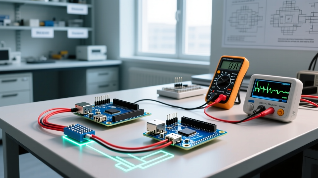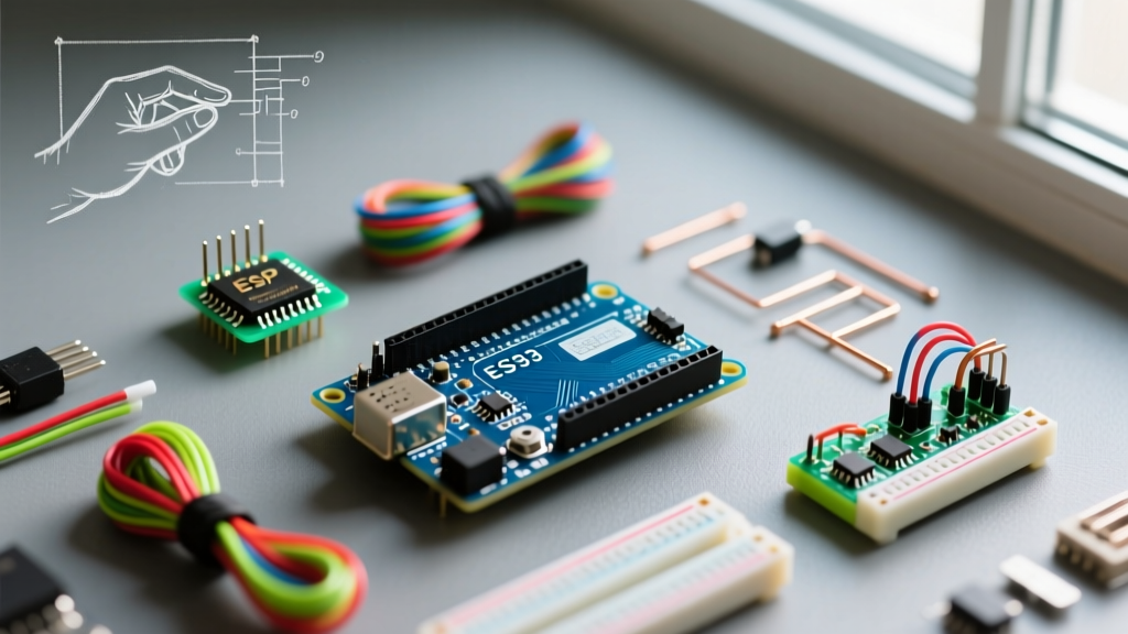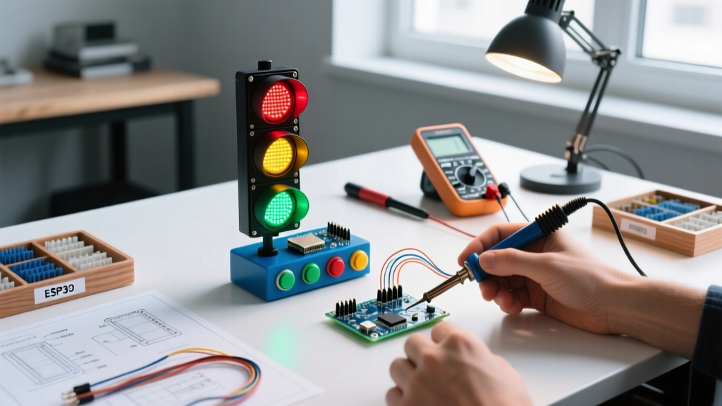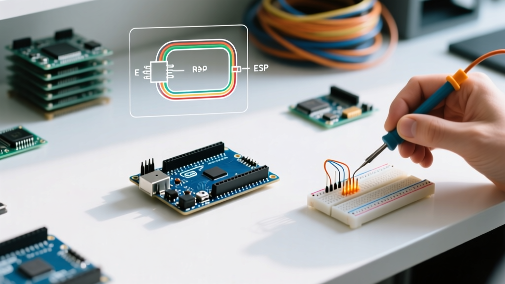

The Core Question: Arduino, What Is It Exactly?
When makers, engineers, and students first encounter the open-source electronics ecosystem, the most common question is: Arduino, what is it? At its most fundamental level, Arduino is a three-part system consisting of a physical programmable circuit board (often referred to as a microcontroller), an Integrated Development Environment (IDE) that runs on your computer, and a massive community-driven library of code.
Unlike proprietary development boards that require expensive, closed-source compilers, Arduino abstracts the complex underlying C and C++ hardware registers into accessible functions like digitalWrite() and analogRead(). As of 2026, the platform has evolved far beyond its original 8-bit AVR roots, integrating 32-bit ARM Cortex-M4 architectures while maintaining the exact same physical footprint and pinout that made it famous.
Hardware Evolution: ATmega328P vs. Renesas RA4M1
To truly understand the platform, you must look at the silicon. For over a decade, the Arduino Uno R3 relied on the Microchip ATmega328P, an 8-bit AVR microcontroller running at 16 MHz. While still available and beloved for legacy projects, the modern standard for beginners is the Arduino Uno R4 series.
The R4 lineup replaces the AVR chip with a 32-bit Renesas RA4M1 (Arm Cortex-M4) clocked at 48 MHz. This provides a massive leap in computational power, allowing for complex floating-point math and advanced signal processing without the need for external digital signal processors (DSPs).
| Feature | Uno R3 (Classic) | Uno R4 Minima | Uno R4 WiFi |
|---|---|---|---|
| Microcontroller | ATmega328P (8-bit) | Renesas RA4M1 (32-bit) | Renesas RA4M1 + ESP32-S3 |
| Clock Speed | 16 MHz | 48 MHz | 48 MHz |
| Flash Memory | 32 KB | 256 KB | 256 KB |
| SRAM | 2 KB | 32 KB | 32 KB |
| 2026 Retail Price | ~$24.00 | ~$27.50 | ~$45.00 |
Critical Warning: 5V vs 3.3V Logic Levels
A common failure mode for beginners transitioning to the R4 WiFi is misunderstanding logic levels. While the Uno R4 operates at 5V for power delivery, the Renesas RA4M1 and the onboard ESP32-S3 are natively 3.3V logic devices. The board includes level shifters on the primary digital I/O pins to tolerate 5V, but if you are using specialized communication protocols like hardware SPI or I2C on secondary pins, you must use a bidirectional logic level converter (like the Texas Instruments TXB0108) to avoid frying the 3.3V silicon.
Step-by-Step: Installing the IDE and Board Cores
Before wiring any sensors, you need to configure your development environment. The Arduino Software Downloads page provides the latest IDE. As of 2026, the Arduino IDE 2.3.x series is the standard, featuring an integrated debugger, serial plotter, and live code linting.
1. Download and Verify the IDE
- Download the IDE 2.3.x installer for your OS (Windows, macOS, or Linux).
- Windows users should verify the digital signature of the installer to ensure it has not been tampered with.
- During installation, allow the installer to add the necessary USB drivers (specifically the CDC-ACM drivers required for virtual COM port communication).
2. Install the Renesas Core
The IDE does not ship with every microcontroller architecture pre-installed to keep the download size manageable. You must pull the board definitions from the cloud.
- Open the IDE and navigate to Tools > Board > Boards Manager.
- Search for
Arduino Renesas RA4M1. - Click Install. This downloads the compiler toolchain, linker scripts, and core C++ libraries specific to the ARM Cortex-M4 architecture.
Pro Tip: For deeper architectural insights and advanced debugging, refer to the official Arduino IDE 2 Documentation, which covers how to interface the IDE with Segger J-Link debuggers for step-by-step firmware execution.
How-To Project: Wiring a DHT22 Temperature Sensor
To move beyond the obligatory "Blink" LED tutorial, let's build a practical environmental monitor. We will interface a DHT22 (AM2302) digital temperature and humidity sensor. Unlike analog thermistors, the DHT22 uses a single-bus digital protocol with strict microsecond timing requirements.
Wiring Matrix
The DHT22 requires a 10kΩ pull-up resistor on the data line to ensure the signal returns to a HIGH state between bits. While some breakout boards include this resistor onboard, bare components do not.
| DHT22 Pin | Arduino Uno R4 Pin | Notes |
|---|---|---|
| 1 (VCC) | 5V | Requires 3.3V to 5.5V. Do not exceed 5.5V. |
| 2 (Data) | Digital Pin 2 | Connect a 10kΩ resistor between VCC and this pin. |
| 3 (NC) | Not Connected | Leave floating. |
| 4 (GND) | GND | Common ground is mandatory for signal reference. |
Writing the Firmware: Setup and Loop
Every Arduino sketch requires two primary functions: setup(), which runs exactly once upon boot or reset, and loop(), which executes continuously. To read the DHT22, we will use the Adafruit DHT library. You can install this via Tools > Manage Libraries by searching for "DHT sensor library".
For comprehensive wiring diagrams and timing diagrams of the single-bus protocol, the Adafruit DHT Sensor Guide remains an authoritative resource for sensor integration.
#include <DHT.h>

#define DHTPIN 2
#define DHTTYPE DHT22

DHT dht(DHTPIN, DHTTYPE);

void setup() {
  Serial.begin(115200);
  while (!Serial) {
    ; // Wait for serial port to connect (crucial for USB-C native boards)
  }
  Serial.println("DHT22 Environmental Monitor Initialized");
  dht.begin();
}

void loop() {
  // Wait 2 seconds between readings (sensor hardware limit)
  delay(2000);

  float h = dht.readHumidity();
  float t = dht.readTemperature(); // Celsius by default

  // Check if any reads failed and exit early (to try again)
  if (isnan(h) || isnan(t)) {
    Serial.println("Failed to read from DHT sensor! Check wiring and pull-up resistor.");
    return;
  }

  Serial.print("Humidity: ");
  Serial.print(h);
  Serial.print("% | Temperature: ");
  Serial.print(t);
  Serial.println(" °C");
}
Why Use 115200 Baud?
Notice the Serial.begin(115200) command. Older tutorials often use 9600 baud. However, modern USB-to-Serial bridges and native USB implementations (like the RA4M1) can handle much higher throughput. Setting the baud rate to 115200 prevents serial buffer overflows when printing high-frequency telemetry data.
Troubleshooting: Fixing 'avrdude' and Upload Errors
When learning what Arduino is and how to use it, you will inevitably encounter compilation or upload errors. Here is how to diagnose the most common hardware communication failures.
Error: "avrdude: stk500_recv(): programmer is not responding"
This error means the IDE cannot establish a handshake with the bootloader on the microcontroller.
- The Cable Trap: Over 60% of these errors are caused by using a "charge-only" USB-C cable. Charge-only cables lack the D+ and D- data lines required for serial communication. Always verify your cable with a smartphone data transfer test.
- Port Selection: Ensure you have selected the correct COM port (Windows) or
/dev/ttyACM0(Linux) under Tools > Port. If the port is greyed out, your OS is not enumerating the USB device. - Bootloader Glitch: On rare occasions, the Renesas bootloader can crash. Double-tap the physical RESET button on the Uno R4 rapidly. This forces the board into ROM bootloader mode, exposing a new COM port specifically for firmware recovery.
Error: "Board at COMX is not available"
This usually occurs if another program is holding the serial port hostage. Close any active Serial Monitors, 3D printer host software (like OctoPrint or Pronterface), or secondary IDE instances that might be polling the port in the background.
Frequently Asked Questions
Is Arduino still relevant in 2026 with the rise of ESP32 and Raspberry Pi Pico?
Absolutely. While the ESP32 offers native Wi-Fi and the Pico offers a lower price point, the Arduino ecosystem's unmatched advantage is its abstraction layer and library support. Furthermore, the Arduino IDE now fully supports compiling code for ESP32 and RP2040 chips, making it a universal hub for microcontroller development.
Can I power the Uno R4 with a 12V battery?
Yes, but with caveats. The Uno R4 features a buck converter that accepts 6V to 24V via the VIN pin or barrel jack. However, drawing high current (over 500mA) from the onboard 5V regulator when supplying 12V will cause severe thermal throttling. For 12V battery projects, it is highly recommended to use an external step-down (buck) module like the LM2596 to drop the battery voltage to a clean 5V before feeding it into the board's 5V pin directly.
What is the difference between a sketch and a library?
A "sketch" is the term Arduino uses for your primary project code file (saved with a .ino extension). A "library" is a collection of pre-written C++ code (usually .h and .cpp files) that provides specialized functions—like I2C communication or sensor parsing—that your sketch can import and utilize without having to write the low-level register commands from scratch.