
The Rite of Passage: When the Arduino Hello World Program Fails
Every maker's journey begins with the Arduino hello world program. In the microcontroller ecosystem, this rite of passage is split into two distinct milestones: the hardware 'Hello World' (the Blink sketch) and the software 'Hello World' (printing text to the Serial Monitor). When these foundational sketches fail, it can halt a project before it even begins. In 2026, with the widespread adoption of the Arduino IDE 2.3.x and the proliferation of diverse clone boards, the failure modes have evolved.
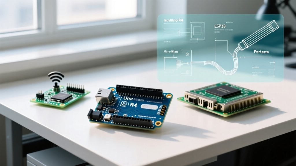
This comprehensive troubleshooting guide bypasses generic advice and dives deep into the electrical and firmware-level reasons why your Arduino hello world program might be failing, providing exact diagnostics for both AVR-based boards (like the Uno R3/R4) and ESP32 development kits.
The Dual Nature of the Arduino Hello World Program
Before troubleshooting, we must define what we are fixing. The term 'Hello World' in the Arduino ecosystem refers to two distinct operations:
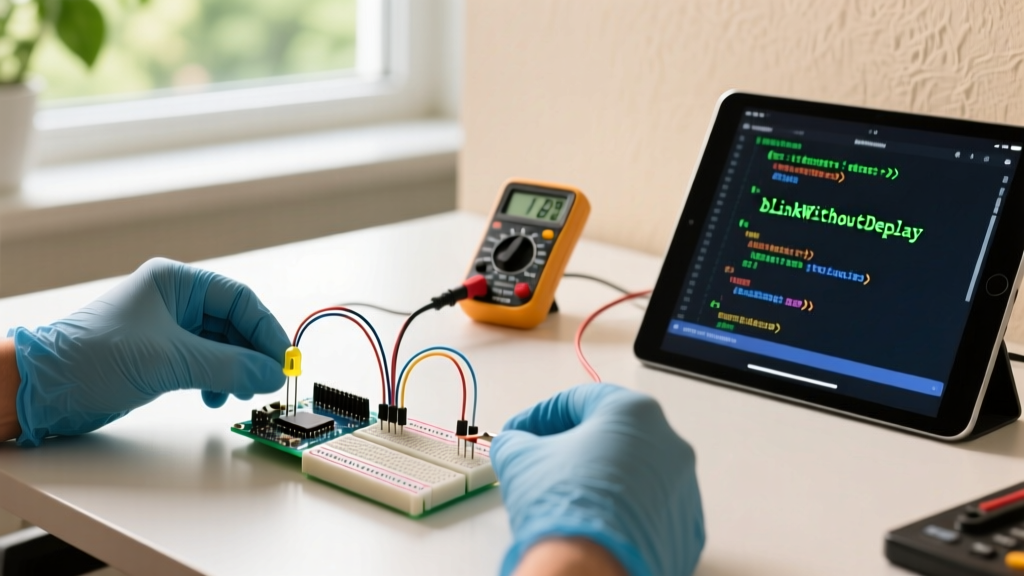
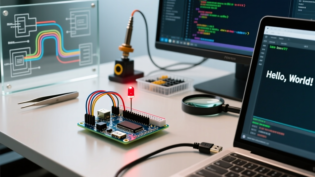
- The Hardware Hello World (Blink): Toggling a GPIO pin HIGH and LOW to flash an onboard LED. This verifies the toolchain, compilation, uploading, and basic GPIO control. According to the official Arduino Blink documentation, this relies on the
LED_BUILTINmacro. - The Software Hello World (Serial Print): Using
Serial.println('Hello World');to send ASCII data over the USB-to-UART bridge. This verifies serial communication, baud rate configurations, and the PC-to-MCU data pipeline.
Troubleshooting the Hardware Hello World (Blink Sketch)
You hit 'Upload', the progress bar completes, but the onboard LED remains stubbornly dark, or stays solidly lit. Here are the specific failure modes and their fixes.
1. The 'Charge-Only' USB Cable Trap
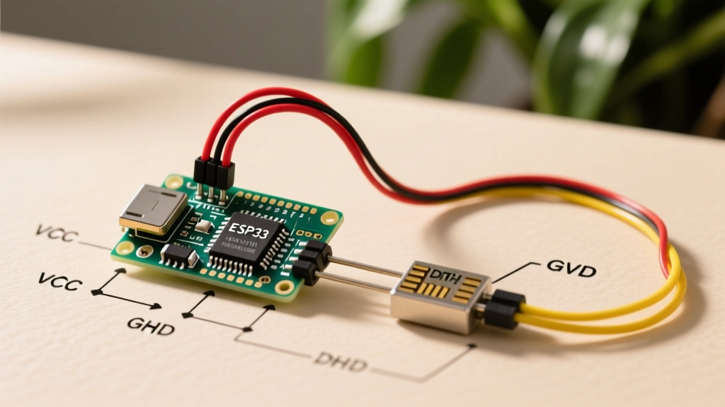
The most common culprit for a failed upload (resulting in the dreaded avrdude: stk500_recv(): programmer is not responding error) is using a charge-only USB cable. Standard USB-A to Micro-USB or USB-C cables require four internal wires: VCC (5V), GND, D+ (Data), and D- (Data). Charge-only cables omit the D+ and D- lines to save manufacturing costs.
- Diagnostic: If your board powers on (LED lights up) but the IDE's 'Select Board' menu shows no available ports, swap to a verified data cable. Keep a dedicated, labeled 'data-only' cable on your workbench.
2. Bootloader Corruption and Auto-Reset Failures
When you click 'Upload' in the IDE, the software pulses the DTR (Data Terminal Ready) line. On a genuine Arduino Uno, this DTR signal is routed through a 0.1µF ceramic capacitor to the RESET pin of the ATmega328P. This brief LOW pulse triggers the bootloader, which listens for new code for exactly 500 milliseconds.
- Edge Case: If the 0.1µF capacitor is damaged, or if you are using a clone board with a flawed auto-reset circuit, the MCU won't reboot into the bootloader. The IDE will time out, throwing an upload error.
- The Fix: Perform a manual reset. Click 'Upload' in the IDE. Watch the TX/RX LEDs. The exact moment the console says
Uploading..., press and release the physical RESET button on the board. This manually triggers the bootloader window, bypassing the broken DTR circuit.
3. The ESP32 Strapping Pin Conflict
If your 'Arduino' is actually an ESP32 DevKit V1, the hardware hello world program targets GPIO 2 (the blue onboard LED). However, GPIO 2 is a critical 'strapping pin'. During boot, the ESP32 checks GPIO 2 to determine the boot mode.
- Failure Mode: If you have external circuitry connected to GPIO 2 that pulls it HIGH, the ESP32 will enter SDIO boot mode instead of Flash boot mode, causing the upload to fail via
esptool.py. - The Fix: Disconnect all external wiring from GPIO 2, GPIO 0, and GPIO 15 before uploading the Blink sketch.
Troubleshooting the Software Hello World (Serial Monitor)
Uploading Serial.begin(9600); Serial.println('Hello World'); seems foolproof until you open the Serial Monitor and see gibberish like ÿÿÿ or ????.
Baud Rate Mismatches in 2026
The SparkFun Serial Communication guide emphasizes that asynchronous serial relies on both devices agreeing on a clock speed. While 9600 baud was the historical standard for AVR boards, modern ecosystems have shifted.
| Microcontroller Platform | Default / Recommended Baud Rate | Common Mismatch Symptom |
|---|---|---|
| Arduino Uno R3 (ATmega328P) | 9600 | Gibberish characters if monitor is set to 115200 |
| Arduino Uno R4 WiFi / Minima | 115200 | Blank screen or slow, corrupted text if set to 9600 |
| ESP32 / ESP8266 DevKits | 115200 | Rapid ???? output if monitor is set to 9600 |
Pro-Tip: In Arduino IDE 2.3.x, the Serial Monitor remembers your last used baud rate. If you switch from an ESP32 project (115200) back to a legacy Uno R3 sketch (9600) without checking the dropdown, your hello world program will appear broken. Always explicitly match the Serial.begin(X) value in your code with the IDE dropdown.
The 'Port Greyed Out' Phenomenon
If the Serial Monitor icon is greyed out, the IDE has lost the COM port handle. This frequently happens on Windows 11 when the OS aggressively suspends USB hubs to save power.
Fix: Open Windows Device Manager, locate your USB-to-Serial COM port, right-click > Properties > Power Management, and uncheck 'Allow the computer to turn off this device to save power'. For Mac users, ensure you have the latest Silicon Labs CP210x VCP drivers installed, as macOS Sonoma and Sequoia tightened kernel extension security.
USB-to-Serial IC Diagnostics: Know Your Clone
Not all Arduino boards use the same USB interface chip. Understanding which IC is on your board is critical for driver troubleshooting. Refer to the Arduino IDE Troubleshooting Hub for deeper OS-specific driver resets.
| USB-to-Serial IC | Common Boards | Driver Status (2026) | Auto-Reset Support |
|---|---|---|---|
| ATmega16U2 | Genuine Uno R3, Mega 2560 | Native CDC-ACM (No driver needed) | Yes (via DTR line) |
| CH340G / CH340C | Elegoo, HiLetgo Uno Clones | WHQL Signed (Auto-installs on Win 10/11) | Yes (via DTR line) |
| CP2102 / CP2104 | NodeMCU, generic ESP8266 | Requires Silicon Labs VCP Driver | Yes (via DTR/RTS logic) |
| CH9102F | Modern ESP32-C3 / ESP32-S3 | Native CDC-ACM (Usually plug-and-play) | Yes (Hardware boot buttons required on some clones) |
Advanced Diagnostic: The Loopback Test
If your Blink sketch works perfectly, but your Serial Hello World prints nothing (and the baud rate is correct), your microcontroller might be fine, but the USB-to-Serial bridge could be dead. You can verify this with a Loopback Test.
- Disconnect the board from power.
- Use a jumper wire to connect the TX pin directly to the RX pin on the board header.
- Connect the board to your PC and open the Serial Monitor.
- Type a character and press Enter.
Result Analysis: If you see the character you typed echoed back on the screen, the USB-to-Serial chip and your PC drivers are functioning perfectly. The fault lies in the main microcontroller (e.g., a fried ATmega328P or a bricked ESP32). If you see nothing, the USB interface chip is damaged, or the USB cable is faulty.
Summary Checklist for a Successful Hello World
Before assuming your hardware is defective, run through this 2026 diagnostic checklist:
- Cable: Verified data-capable USB cable (not charge-only).
- Port: Correct COM port selected in IDE 2.3.x (check Device Manager if unsure).
- Board Definition: Exact board model selected (e.g., 'Uno R4 WiFi' vs 'Uno R3'). Selecting the wrong board alters the compilation memory map and upload protocol.
- Baud Rate: Serial Monitor dropdown matches the
Serial.begin()integer. - Strapping Pins: No external components attached to GPIO 0, 2, or 15 on ESP-based boards during upload.
Mastering the troubleshooting of the Arduino hello world program builds the foundational electrical intuition required for complex robotics and IoT deployments. By understanding the physical layer (DTR capacitors, USB data lines) and the protocol layer (baud rates, CDC-ACM drivers), you transform from a passive code-copier into a capable embedded systems engineer.