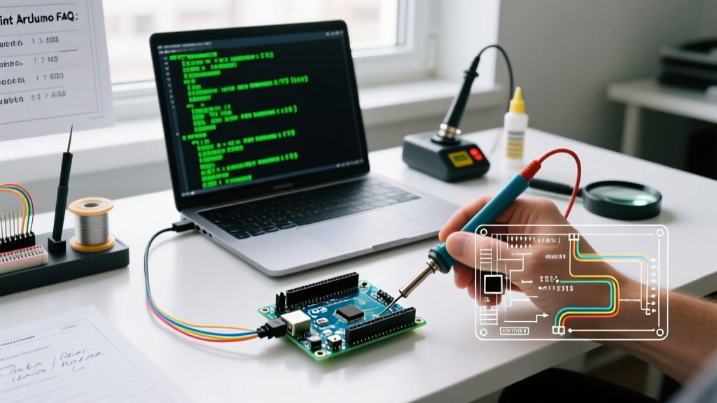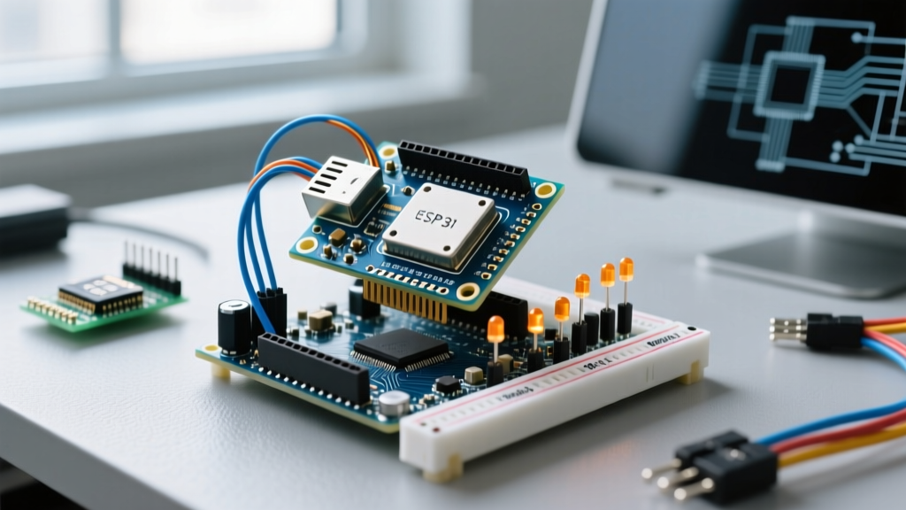

The 'Arduino Hat' Misnomer: Understanding the Hardware Divide
If you have been searching for an Arduino Hat, you have likely encountered a frustrating wall of incompatible products. In the maker community, the term 'Hat' is frequently—but incorrectly—used as a catch-all for any microcontroller add-on board. To approach compatibility with engineering precision, we must first clarify the nomenclature. Raspberry Pi utilizes HATs (Hardware Attached on Top), which conform to a strict 40-pin GPIO standard. Arduino, conversely, utilizes Shields, which stack via female headers on the Uno, Mega, or Nano form factors.
There is no such thing as a native 'Arduino Hat.' However, makers frequently need to adapt a Raspberry Pi HAT (like the popular Sense HAT or PoE HAT) for use with an Arduino microcontroller. This compatibility guide bridges that gap, detailing the electrical hazards, physical workarounds, and logic-level translations required to safely integrate Pi HATs into Arduino ecosystems in 2026.
Physical and Electrical Specifications: HAT vs. Shield
Before wiring any cross-platform hardware, you must understand the fundamental architectural differences. According to the official Raspberry Pi HAT Design Guide, a true HAT requires an ID EEPROM connected to GPIO 27 and 28 for automatic board configuration. Arduino Shields lack this auto-configuration feature entirely, relying instead on manual library initialization in the IDE.
| Feature | Raspberry Pi HAT Standard | Arduino Shield (Uno R3/R4) |
|---|---|---|
| Physical Header | 40-pin (2x20) male shrouded | Female stacking (15-pin + 21-pin) |
| Native Logic Level | 3.3V | 5V (Uno R3), Mixed 5V/3.3V (Uno R4) |
| I2C Bus Pins | GPIO 2 (SDA), GPIO 3 (SCL) | A4 (SDA), A5 (SCL) / Dedicated SDA/SCL |
| SPI Bus Pins | GPIO 9, 10, 11 | D11, D12, D13 |
| Auto-Configuration | Yes (ID EEPROM on GPIO 27/28) | No (Manual #define in code) |
| Power Input Requirement | 5V on Pin 2/4 (HAT steps down to 3.3V) | 5V via USB or Barrel Jack (7-12V) |
The Voltage Danger Zone: 3.3V vs 5V Logic
The most critical failure mode when adapting a Pi HAT for an Arduino is logic level mismatch. Most standard Arduinos (like the classic Uno R3 or Mega 2560) operate at 5V logic. Raspberry Pi HATs are strictly 3.3V devices. As detailed in SparkFun's comprehensive guide on logic levels, feeding a 5V digital signal into a 3.3V microcontroller or sensor IC will exceed the absolute maximum ratings of the silicon's GPIO protection diodes.
⚠️ CRITICAL WARNING: Never connect a 5V Arduino SDA/SCL line directly to a 3.3V Pi HAT without a bi-directional logic level shifter. Doing so will degrade the HAT's I2C transceivers over time or instantly destroy the GPIO pins if the injection current exceeds 3.3mA.
If you are using the newer Arduino Uno R4 Minima or WiFi, you are dealing with a Renesas RA4M1 ARM Cortex-M4 processor that operates natively at 5V, though it features a dedicated 3.3V output pin and some 3.3V-tolerant I/O. However, for reliable I2C/SPI communication with a Pi HAT, dedicated level translation remains mandatory.
Step-by-Step Adaptation Guide: Bridging the Gap
To successfully use a Pi HAT with an Arduino, you must bypass the physical header incompatibility and translate the voltage. Here is the most reliable, field-tested method using a breadboard, a Pi Cobbler, and a logic level shifter.
Materials Required (Estimated Cost: $15 - $22)
- Adafruit Pi Cobbler Plus (~$8.00): Breaks out the 40-pin HAT header to a standard breadboard.
- TXS0108E Logic Level Shifter Breakout (~$4.50): An 8-channel bi-directional shifter by Texas Instruments, perfect for I2C, SPI, and UART.
- Solderless Breadboard & Jumper Wires (~$5.00).
- Arduino Nano 33 IoT or Uno R4 (Base MCU).
Wiring Procedure
- Seat the Cobbler: Plug the Pi Cobbler into the breadboard. If you are testing a physical Pi HAT, plug the HAT directly into the Cobbler's male pins.
- Route Power: Pi HATs expect 5V on Pins 2 and 4 to power their onboard LDOs (Low Dropout Regulators), which then generate the 3.3V logic rail. Connect the Arduino's 5V pin to the Cobbler's 5V rail, and GND to GND. Do not power the HAT solely from the Arduino's 3.3V pin; it cannot supply the required current (often >300mA).
- Wire the Level Shifter: Connect the TXS0108E's 'VA' side to the Arduino's 5V logic, and the 'VB' side to the HAT's 3.3V logic.
- Map the Data Lines: Run the Arduino's I2C lines (SDA/SCL) through the level shifter to the HAT's GPIO 2 and GPIO 3. Run SPI lines (MOSI, MISO, SCK, CS) through the remaining shifter channels.
- Handle the EEPROM: Because the Arduino lacks the Raspberry Pi's OS-level device tree overlay system, the HAT's ID EEPROM will be ignored. You must manually identify the HAT's onboard sensors and write or port the C++ I2C/SPI initialization code in the Arduino IDE.
Edge Cases and Troubleshooting
Even with correct voltage translation, cross-platform hardware adaptation introduces specific edge cases that trip up intermediate makers.
I2C Pull-Up Resistor Collisions
Almost all Raspberry Pi HATs feature onboard 1.8kΩ or 2.2kΩ pull-up resistors tied to 3.3V on the SDA and SCL lines. The Arduino Uno R4 also features internal pull-ups. When combined, the parallel resistance can drop too low, causing the I2C bus to fail to recognize HIGH states. Fix: Use a multimeter to check the HAT's schematic. If 1.8kΩ pull-ups are present, disable the Arduino's internal pull-ups in your code using digitalWrite(SDA, LOW); after Wire.begin(); or physically snip the pull-up traces on the HAT if you are desperate.
SPI Clock Speed Mismatches
Pi HATs designed for the Raspberry Pi 4 or 5 often expect SPI clock speeds upwards of 16 MHz to 32 MHz. Standard 8-bit Arduinos (like the Uno R3) max out around 8 MHz reliably on the SPI bus. If your Pi HAT uses a high-speed ADC or DAC, you must upgrade to an ARM-based Arduino (like the Portenta H7 or Nano 33 IoT) to achieve the necessary clock dividers.
Frequently Asked Questions
Can I plug a Raspberry Pi PoE HAT into an Arduino?
No. Pi PoE HATs utilize the 40-pin header's specific Ethernet PoE pins (which are only present on the Pi 3B+ and newer) to negotiate power via an isolated flyback converter. Arduinos lack the physical Ethernet data lines required to trigger the PoE negotiation handshake, rendering the HAT useless for power delivery on an MCU.
Is there an adapter board that converts Arduino Shields to Pi HATs?
While no single monolithic PCB exists due to the vast pinout differences, companies like SparkFun and Adafruit sell 'Pi-to-Arduino' shield adapters. These are essentially passive breakout boards that route the 40-pin Pi header to standard Arduino female stacking headers. However, they do not include logic level shifters, meaning they are only safe to use if your Arduino is a native 3.3V board (like the Arduino Zero).
Why does my Pi HAT's LED matrix flicker on the Arduino?
Flickering on LED matrices (like the Sense HAT) usually indicates a power brownout. The Arduino's onboard 5V linear regulator can typically only supply 500mA to 800mA before thermal throttling. An 8x8 RGB matrix pulling white light can draw over 1A. You must inject external 5V power directly into the breadboard's power rails to stabilize the HAT.