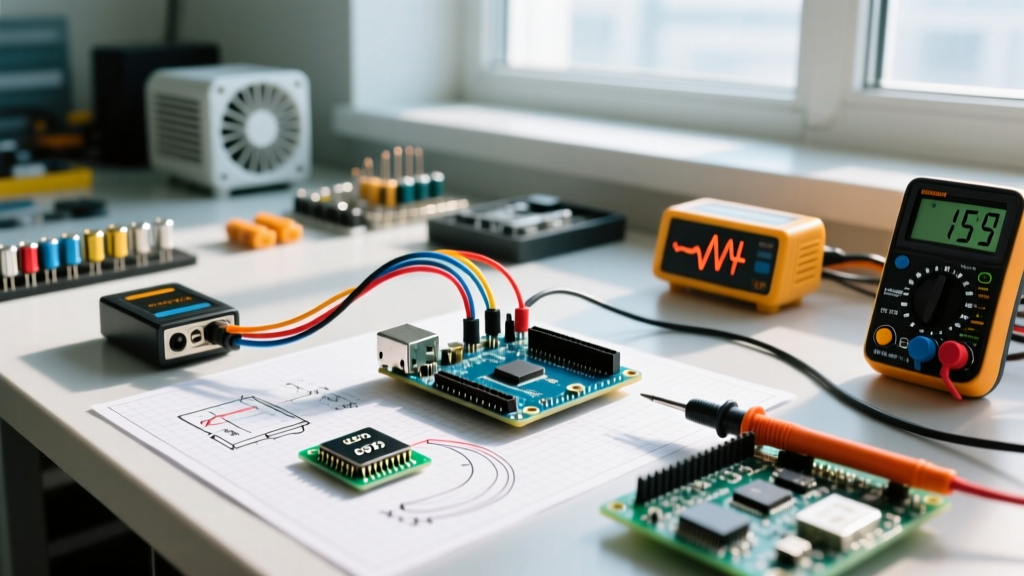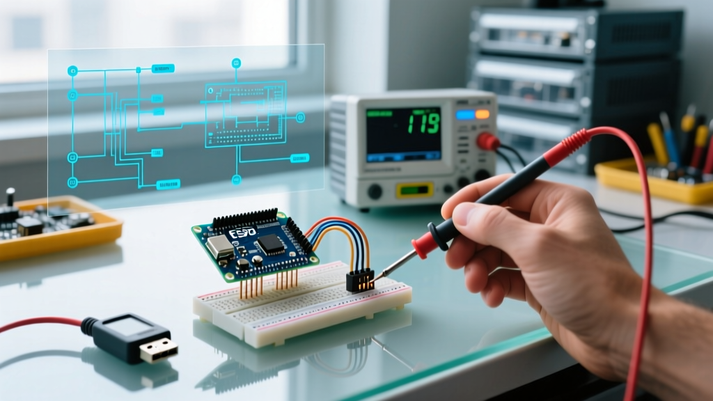

Why Build an Arduino Morse Code System?
While digital modes like FT8 dominate modern amateur radio, continuous wave (CW) Morse code remains a highly efficient, low-bandwidth communication method. Building an Arduino Morse code translator and transmitter is an excellent exercise in embedded timing, RF (Radio Frequency) fundamentals, and memory-efficient data structures. Whether you are building an automated beacon, a practice oscillator, or a digital keyer for an HF transceiver, this tutorial provides a professional-grade approach to encoding, transmitting, and interfacing with real-world radio hardware.
In this guide, we move beyond basic LED-blinking sketches. We will calculate precise ITU-standard timing, tune a quarter-wave antenna for 433MHz ASK transmission, and use an optocoupler to safely key a high-voltage amateur radio transceiver without destroying the microcontroller.
Hardware Selection and Bill of Materials
To ensure reliable timing and adequate SRAM for string manipulation, we recommend the Arduino Nano Every over the legacy ATmega328P-based Nano. The Nano Every utilizes the ATmega4809, offering 6KB of SRAM and superior hardware timer capabilities, which prevents the 'tone-blocking' jitter common in older AVR boards.
| Component | Model / Specification | Est. Price (2026) | Purpose |
|---|---|---|---|
| Microcontroller | Arduino Nano Every (ATmega4809) | $12.50 | Core logic and timing generation |
| RF Transmitter | SYN115 433MHz ASK Module | $1.80 | Wireless beacon transmission |
| Audio Feedback | Passive Piezo Buzzer (5V) | $0.90 | Local sidetone monitoring |
| Optocoupler | PC817 (for HF Radio Interfacing) | $0.20 | Galvanic isolation for CW keying |
| Resistors | 220Ω and 1kΩ (1/4W) | $0.10 | Current limiting for LED/Buzzer/Opto |
The Mathematics of Morse: ITU Timing Standards
A common failure mode in DIY Arduino Morse projects is arbitrary timing. To ensure your transmission is legible to both human operators and automated software decoders, you must adhere to the International Telecommunication Union (ITU) standard. The standard word used to calculate Morse speed is 'PARIS', which consists of exactly 50 elements (dits, dahs, and spaces).
According to the ITU standard documented on Wikipedia, the timing ratios are strictly defined:
- Dit (dot): 1 unit
- Dah (dash): 3 units
- Intra-character space: 1 unit (between dits/dahs in the same letter)
- Inter-character space: 3 units (between letters)
- Word space: 7 units (between words)
Calculating the Dit Length in Milliseconds
If you want to transmit at a standard beginner speed of 15 Words Per Minute (WPM), the math is straightforward:
- 15 WPM × 50 elements/word = 750 elements per minute.
- 60,000 ms / 750 elements = 80 ms per unit (dit).
- Therefore, at 15 WPM: Dit = 80ms, Dah = 240ms, Letter Space = 240ms, Word Space = 560ms.
Hardcoding these values into your sketch as const int DIT_LENGTH = 80; ensures perfect cadence.
Wiring the 433MHz RF Module and Antenna Tuning
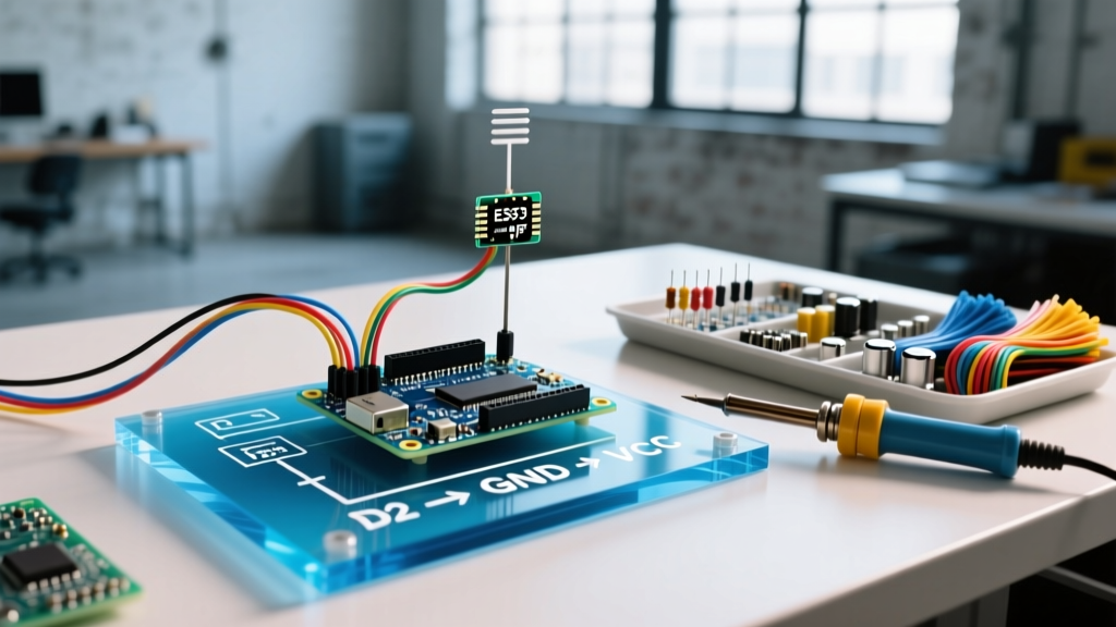
The SYN115 433MHz ASK (Amplitude Shift Keying) transmitter is a low-cost module, but its range is entirely dependent on the antenna. Most tutorials suggest attaching a random piece of wire, resulting in a dismal 2-meter range. To achieve 50+ meters of line-of-sight range, you must use a tuned quarter-wave antenna.
Expert Tip: The speed of light (c) is roughly 300,000,000 m/s. The wavelength (λ) for 433MHz is λ = c / f = 300 / 433 = 0.692 meters. A quarter-wave antenna is λ / 4 = 0.173 meters (17.3 cm). Solder exactly 17.3 cm of 22 AWG stranded wire to the ANT pad on the SYN115 module.
Pinout Configuration
Connect the hardware to the Arduino Nano Every as follows:
- SYN115 VCC: 5V (Do not use 3.3V; the RF output power drops significantly).
- SYN115 GND: GND.
- SYN115 DATA: Digital Pin 4.
- Piezo Buzzer (+): Digital Pin 5 (via 220Ω resistor).
- Piezo Buzzer (-): GND.
Integrating with Ham Radio Transceivers (The Safe Way)
If your goal is to use this Arduino Morse keyer to transmit via a real HF radio (like an Icom IC-7300 or Yaesu FT-991A), never connect the Arduino GPIO pin directly to the radio's CW KEY jack. Many transceivers pull the key line up to 5V, 8V, or even 12V. Back-feeding this voltage into your Nano Every will instantly destroy the ATmega4809 microcontroller.
Instead, use a PC817 optocoupler for galvanic isolation:
- Connect Arduino Pin 6 to a 220Ω resistor, then to the PC817 Anode (Pin 1).
- Connect PC817 Cathode (Pin 2) to Arduino GND.
- Connect PC817 Collector (Pin 4) to the Radio's CW Key input.
- Connect PC817 Emitter (Pin 3) to the Radio's Ground.
When the Arduino pin goes HIGH, the internal LED illuminates, triggering the phototransistor and pulling the radio's key line to ground safely. For comprehensive safety guidelines on equipment interfacing, always consult the American Radio Relay League (ARRL) technical documentation regarding transceiver keying voltages.
Core Logic: Binary Tree Decoding vs. Array Lookup
When writing the C++ sketch for an Arduino Morse translator, beginners often use a 1D array of strings (e.g., String morse[] = {'.-', '-...', ...'}). This approach is highly inefficient on microcontrollers. String comparison in a loop consumes excessive CPU cycles and fragments the limited SRAM heap.
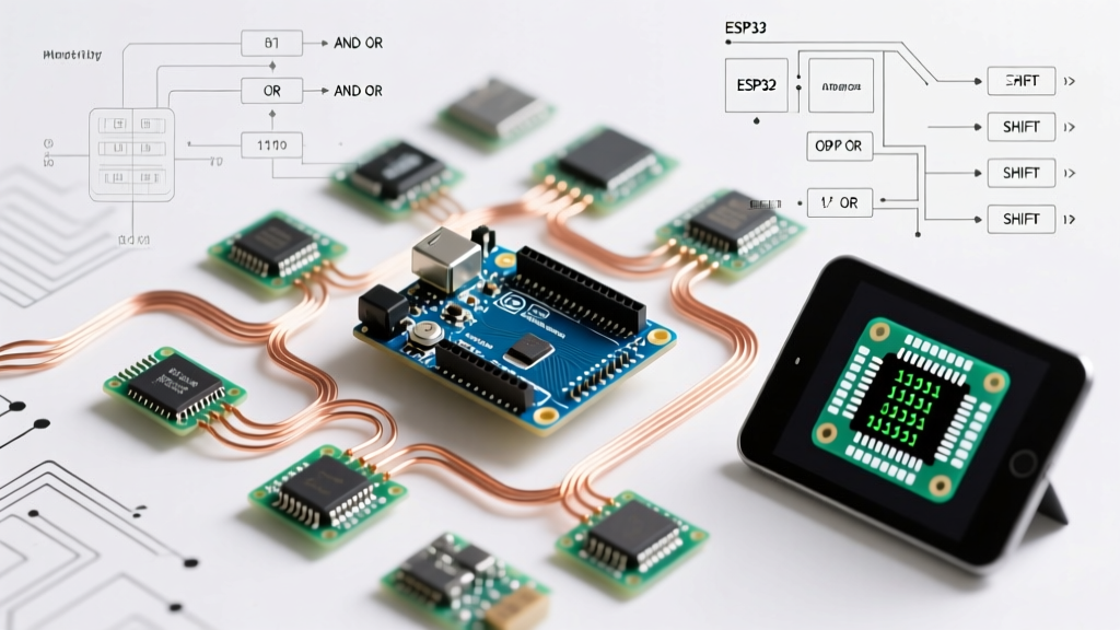
The professional approach is to use a Binary Tree (Huffman-like structure) for decoding Morse back into ASCII, and a bitmask array for encoding ASCII to Morse.
The Encoding Bitmask Method
For encoding (Text to Morse), store the Morse characters as binary integers. A '1' represents a dah, a '0' represents a dit, and the most significant '1' acts as a sentinel (start bit) to indicate the length of the sequence. For example, the letter 'A' (.-) is binary 101 (Sentinel 1, Dit 0, Dah 1). The letter 'B' (-...) is 11000. This reduces the entire alphabet to a lightweight integer array, saving hundreds of bytes of SRAM.
Real-World Troubleshooting and Edge Cases
Even with perfect wiring, embedded RF projects present unique edge cases. Here is how to diagnose the most common issues encountered in 2026 maker spaces:
1. Timing Jitter and Audio Distortion
Symptom: The piezo buzzer sounds 'warbled' or the transmitted RF Morse code is decoded as erratic characters by software like FLDIGI.
Cause: Using the delay() function blocks the main loop, causing software serial or RF modulation timers to miss interrupts.
Solution: Implement a non-blocking state machine using millis(). Track the state of the current character (e.g., STATE_DIT_ON, STATE_SPACE_OFF) and toggle pins only when the delta time exceeds the calculated ITU unit length.
2. RF Transmitter Overheating and Range Drop
Symptom: The SYN115 module works for 30 seconds, then the range drops from 50 meters to 2 meters, and the chip is hot to the touch.
Cause: Transmitting a continuous 'dah' or a solid carrier wave without modulation pauses causes the ASK transmitter's oscillator to overheat, shifting the resonant frequency away from 433.92MHz.
Solution: Ensure your code enforces a mandatory 1-unit (80ms) intra-character space between every dit and dah. Never transmit a solid HIGH signal to the DATA pin for longer than 3 units (240ms at 15 WPM).
3. Ground Loop Hum in Audio Sidetone
Symptom: A loud 60Hz/50Hz hum is audible through the piezo buzzer or connected headphones.
Cause: Sharing a thin ground wire between the high-current RF transmitter and the sensitive audio piezo.
Solution: Use a star-ground topology. Run separate ground wires from the RF module GND and the Buzzer GND directly to the Arduino's central GND pin, rather than daisy-chaining them on a breadboard rail.
Conclusion
Building an Arduino Morse translator bridges the gap between historical communication techniques and modern embedded systems engineering. By calculating exact ITU timing, tuning your RF antenna to a precise 17.3cm quarter-wave, and utilizing memory-efficient bitmask encoding, you elevate a simple hobby project into a robust, field-ready communication tool. Whether you are deploying an automated 433MHz telemetry beacon or safely keying a 100W HF transceiver via an optocoupler, the principles of strict timing and hardware isolation remain the keys to success.