
The Silent Failures of Arduino CAN Shields
The Controller Area Network (CAN) bus is the undisputed backbone of automotive and industrial telemetry. When you attach an Arduino CAN shield to your microcontroller, you expect robust, noise-immune communication. However, the reality of prototyping with MCP2515-based shields is often fraught with silent failures, dropped frames, and cryptic initialization errors. Unlike UART or I2C, a misconfigured CAN node doesn't just fail to send data; it can trigger a 'Bus-Off' state, effectively disconnecting itself from the network to protect other nodes.
In 2026, the market is flooded with varied CAN shield clones. While the Seeed Studio CAN-BUS Shield V2 remains a premium benchmark, budget boards often swap out critical components without updating the silkscreen, leading to severe voltage and timing mismatches. This guide provides a deep-dive diagnostic framework for troubleshooting Arduino CAN shield errors, moving beyond basic wiring checks into SPI clock domains, transceiver logic levels, and MCP2515 error register decoding.
Anatomy of a CAN Shield Failure: Controller vs. Transceiver
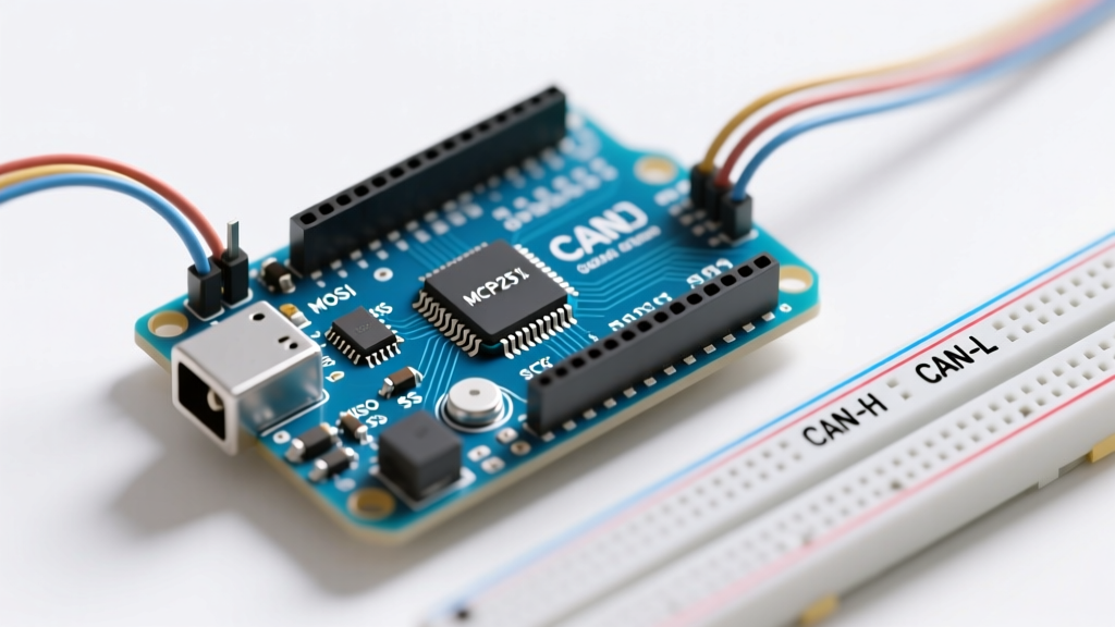
To diagnose an error, you must isolate the fault domain. An Arduino CAN shield consists of two primary silicon components:
- The CAN Controller (Microchip MCP2515): Handles the CAN protocol, frame arbitration, and error checking. It communicates with the Arduino via SPI.
- The CAN Transceiver (e.g., MCP2551, SN65HVD230, or TJA1050): Translates the 3.3V/5V digital logic from the controller into the differential analog voltages (CANH and CANL) required by the physical bus.
If your Arduino serial monitor prints CAN Init Failed, the issue is almost exclusively between the Arduino and the MCP2515 (SPI domain). If the initialization succeeds but no messages are received or transmitted, the fault lies in the physical layer (transceiver, termination, or bus topology).
Diagnostic Phase 1: The 'Init Failed' Epidemic
The most common error encountered when deploying an Arduino CAN shield is the failure of the MCP2515 to initialize. This is rarely a hardware defect; it is almost always a configuration mismatch regarding the SPI bus or the oscillator crystal.
1. The Crystal Oscillator Mismatch
The MCP2515 requires an external crystal to generate its internal clock and CAN bit-timing. Shields are manufactured with either an 8 MHz or 16 MHz crystal. If your code assumes 16 MHz but the shield has an 8 MHz crystal, the baud rate will be halved, and the initialization sequence may time out or fail synchronization.
Expert Tip: Always visually inspect the silver oscillator can on the shield. If it reads '8.000', you must define your library initialization accordingly. Using the industry-standard autowp/arduino-mcp2515 library, your setup must explicitly declare the crystal frequency: mcp2515.setBitrate(CAN_500KBPS, MCP_8MHZ);2. SPI Clock Speed Violations
The MCP2515 has a maximum SPI clock frequency of 10 MHz. If you are using a 16 MHz Arduino Uno, the default SPI clock divider might push the bus speed too high, or edge-timing skew may corrupt the initialization registers. If you experience intermittent initialization failures, explicitly set the SPI clock divider in your setup routine:
SPI.setClockDivider(SPI_CLOCK_DIV4); // Yields 4 MHz on a 16MHz Uno
3. The 3.3V vs 5V Logic Level Trap
The MCP2515 is a 5V device. If you are using an Arduino CAN shield with a 3.3V microcontroller (like the Arduino Due, Nano 33 IoT, or an ESP32 adapter), the 3.3V MOSI and SCK signals may fall below the MCP2515's V_IH (High-level input voltage) threshold, which is typically 2.0V but can be marginal on noisy breadboards. If your shield lacks a built-in logic level shifter, you must use a bidirectional level translator (like the BSS138 or TXB0104) on the SPI lines.
Diagnostic Phase 2: Physical Layer and Transceiver Faults
If the MCP2515 initializes successfully but the bus is silent, the error has migrated to the physical layer. According to the Microchip MCP2515 Datasheet, the controller will silently drop frames if the transceiver fails to acknowledge the dominant state.
Transceiver Voltage and Pinout Inconsistencies
Budget Arduino CAN shields frequently substitute the original 5V MCP2551 transceiver with the 3.3V SN65HVD230 or TJA1050. While this makes the shield compatible with 3.3V logic, it alters the physical layer characteristics. Use a multimeter to measure the DC resting voltages between the transceiver pins and Ground:
| Transceiver Model | CANH Resting (Recessive) | CANL Resting (Recessive) | VCC Requirement |
|---|---|---|---|
| MCP2551 | ~2.5V | ~2.5V | 5.0V |
| SN65HVD230 | ~2.3V | ~2.3V | 3.3V |
| TJA1050 | ~2.5V | ~2.5V | 5.0V |
Note: If you measure 0V or 5V on CANH/CANL while the bus is idle, the transceiver is either unpowered, in 'Silent/Standby' mode, or destroyed.
The Termination Resistor Matrix
CAN bus requires a 120-ohm termination resistor at each physical end of the bus to prevent signal reflection. Most Arduino CAN shields include a 120-ohm resistor (often labeled R1 or R7) and a jumper pad or switch to enable/disable it.
- Diagnostic Check: With the power off, measure the resistance between CANH and CANL on the DB9 or screw terminal. You should read approximately 60 ohms if two nodes are connected and both have their termination jumpers closed (120Ω || 120Ω = 60Ω).
- The 'Bus-Off' Trigger: If you read 120 ohms, you only have one node terminated. If you read near 0 ohms, you have a short circuit. If you read infinite resistance (OL), your termination is missing, causing high-frequency ringing that the MCP2515 interprets as bit errors, rapidly filling its error counters and forcing a Bus-Off state.
Diagnostic Phase 3: Decoding the MCP2515 Error Registers
When communication degrades, the MCP2515 tracks errors using internal counters (TEC for Transmit, REC for Receive). When these counters cross specific thresholds, the controller changes state. You can read the EFLG (Error Flag) register via your Arduino library to pinpoint the exact nature of the degradation.
| EFLG Bit | Flag Name | Diagnostic Meaning & Action Required |
|---|---|---|
| Bit 7 | RX1OVR | Receive Buffer 1 Overflow: Your Arduino sketch is reading messages too slowly. Increase SPI polling rate or use interrupt-driven reading. |
| Bit 6 | RX0OVR | Receive Buffer 0 Overflow: Same as above. The MCP2515 dropped incoming frames because the Arduino didn't empty the buffer. |
| Bit 5 | TXBO | Transmit Bus-Off: TEC exceeded 255. The node has disconnected itself. Check for CANH/CANL shorts, missing termination, or severe baud rate mismatch. |
| Bit 4 | TXEP | Transmit Error-Passive: TEC > 127. The node can still transmit but is isolated from active error flagging. |
| Bit 3 | RXEP | Receive Error-Passive: REC > 127. Often caused by a noisy bus or ground loop. |
| Bit 2 | TXWAR | Transmit Error Warning: TEC > 95. Approaching error-passive state. |
| Bit 1 | RXWAR | Receive Error Warning: REC > 95. Approaching error-passive state. |
| Bit 0 | EWARN | Error Warning: Either TEC or REC has exceeded 95. |
To recover from a TXBO (Bus-Off) state, the MCP2515 requires 128 occurrences of 11 consecutive recessive bits. In software, you often need to force a reset of the MCP2515 via the SPI reset command (mcp2515.reset()) to clear the error counters and rejoin the bus.
Advanced Troubleshooting: Ground Loops and Common-Mode Voltage
A frequently overlooked cause of Arduino CAN shield failure is the violation of the common-mode voltage range. While CAN is a differential protocol, the transceiver's ground reference must remain within a specific tolerance relative to the bus ground.
If your Arduino is powered by a switching power supply or is connected to a high-current load (like a motor controller), the local ground potential may shift. The ISO 11898 standard dictates that the common-mode voltage must stay within -2V to +7V. If the ground differential between your Arduino shield and the rest of the CAN network exceeds this, the transceiver's internal protection diodes will clamp the signal, resulting in severe waveform distortion and continuous CRC (Cyclic Redundancy Check) errors.
The Fix: Always run a dedicated, heavy-gauge ground wire alongside your CANH/CANL twisted pair to tie the Arduino shield's GND directly to the main network ground star-point. Do not rely solely on the DB9 connector shell for grounding.
Frequently Asked Questions (FAQ)
Why is my Arduino CAN shield getting hot to the touch?
If the MCP2515 or the transceiver is too hot to touch, you likely have a short circuit between CANH and VCC, or CANL and Ground. Alternatively, if you are using a 5V transceiver (MCP2551) but accidentally feeding the shield's VCC pin with 12V from an external automotive source, the onboard 5V linear regulator (often an AMS1117-5.0) will overheat and fail. Always verify your shield's voltage input limits.
Can I connect multiple Arduino CAN shields to the same SPI bus?
Yes, but it requires careful error diagnosis. The MCP2515 shares the MISO, MOSI, and SCK lines, but each shield must have a unique Chip Select (CS) pin and a unique Interrupt (INT) pin. Furthermore, daisy-chaining SPI devices increases capacitive load, which may require you to lower the SPI clock speed to 2 MHz or 4 MHz to prevent signal degradation and initialization errors.
My shield initializes, but it only receives messages, never transmits. Why?
This is the classic symptom of a missing ground connection or a 'Listen-Only' mode configuration. Check your library initialization code to ensure you haven't accidentally enabled the MCP2515's Listen-Only mode (used for passive bus sniffing). If the software is correct, verify that the transceiver's RS (Slope Control) pin is tied to Ground. If the RS pin is left floating or pulled high, the transceiver enters Standby or Listen-Only mode, disabling the CANH/CANL transmit drivers.