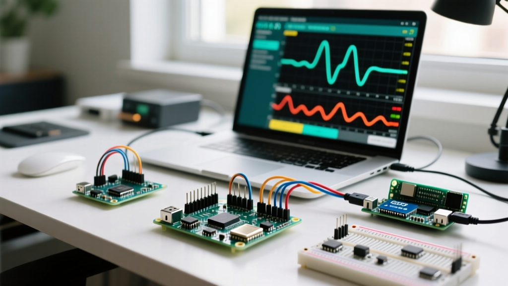

The Paradigm Shift: Why Deploy an Arduino as a PLC?
Historically, industrial automation has been gated by high hardware costs and proprietary software ecosystems. A standard Siemens S7-1200 or Allen-Bradley MicroLogix PLC can easily cost between $400 and $800 before adding I/O expansion modules, proprietary programming cables, and licensing fees. Today, utilizing an Arduino as a PLC represents a massive workflow optimization for small-to-medium enterprises (SMEs), agile manufacturing cells, and advanced makers. By leveraging open-source toolchains and industrial-grade microcontroller hardware, engineers can slash deployment costs by up to 70% while maintaining rigorous reliability standards.
However, simply plugging a bare Arduino Uno into a 24V industrial control panel is a recipe for catastrophic failure. Optimizing your workflow requires a deliberate transition from hobbyist prototyping to industrial systems engineering. This guide breaks down the exact hardware selection, software standardization, and electrical hardening workflows required to successfully deploy Arduino-based PLCs in production environments in 2026.
Hardware Selection Matrix: Bare Boards vs. Industrial Modules
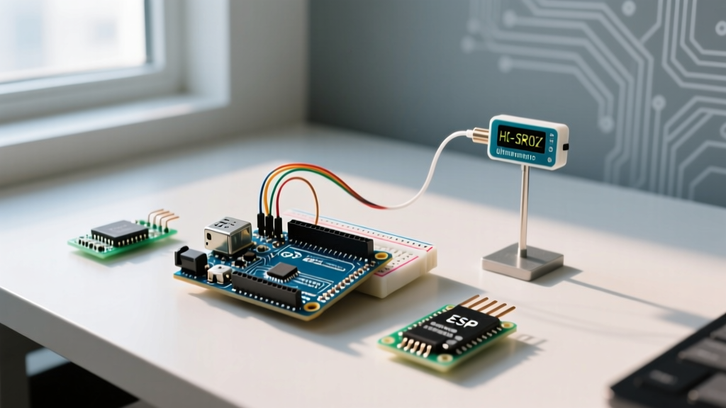
The first step in workflow optimization is selecting the right physical platform. While a bare ATmega2560 board costs under $30, the engineering hours required to design custom optoisolation, 24V logic translation, and DIN-rail mounting far outweigh the hardware savings. Modern industrial Arduino PLCs solve this by integrating galvanic isolation and industrial power supplies directly onto the PCB.
| Hardware Platform | Core Architecture | I/O Isolation | Est. Price (2026) | Best Workflow Use Case |
|---|---|---|---|---|
| Arduino Opta (WiFi/Lite) | STM32H747XI (Dual-Core) | Native 24V Galvanic | $175 - $225 | Native IEC 61131-3, secure IIoT integration |
| Industrial Shields ESP32 PLC | ESP32-WROVER | Optoisolated Digital I/O | $140 - $160 | High-speed custom C++ automation, OTA updates |
| Bare Mega2560 + Relay Shield | ATmega2560 | None (Direct Logic) | $35 - $45 | Low-voltage (5V/12V) maker prototypes only |
For professional deployments, the Arduino Opta documentation highlights its native compatibility with the Arduino PLC IDE, which supports IEC 61131-3 languages. If your workflow relies heavily on custom C++ libraries or requires aggressive cost-cutting, the ESP32-based modules from Industrial Shields offer a compelling middle ground, featuring built-in relays and analog inputs rated for 10-24V DC environments.
Software Workflow: Transitioning to IEC 61131-3
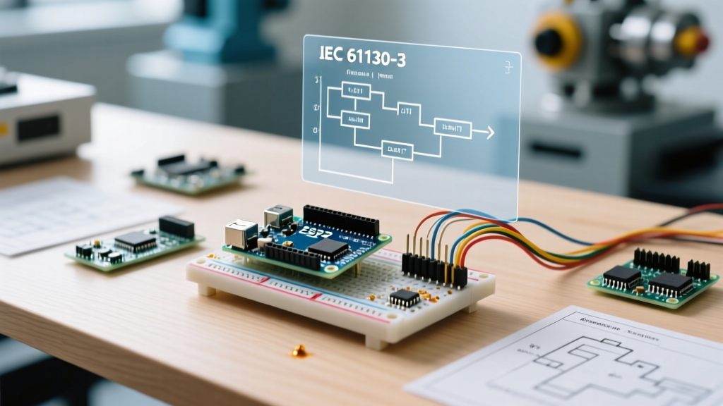
The most significant bottleneck in DIY automation is 'spaghetti code'—unmaintainable C++ sketches that lock the original author into a permanent maintenance role. To optimize team workflows and ensure long-term maintainability, you must transition to the IEC 61131-3 standard, which utilizes Ladder Diagram (LD), Function Block Diagram (FBD), and Structured Text (ST).
Option A: The Arduino PLC IDE (CODESYS Engine)
If you are using the Arduino Opta, the official Arduino PLC IDE provides a seamless, licensed CODESYS environment. This allows automation engineers trained on traditional PLCs to program the Opta using familiar Ladder Logic without learning C++ pointers or memory management.
Option B: OpenPLC for Open-Source Flexibility
For ESP32 or Mega2560-based systems, the OpenPLC Project Repository is the industry standard for open-source automation. OpenPLC allows you to write standard Ladder Logic in a desktop editor, compile it, and flash it to your Arduino-based hardware.
Workflow Tip: Never mix raw C++ interrupt service routines (ISRs) with OpenPLC scan cycles unless absolutely necessary. OpenPLC relies on a predictable, deterministic scan loop (typically 2ms to 10ms). Injecting asynchronous C++ interrupts can cause race conditions in your Ladder Logic state machines.
Electrical Hardening: Avoiding Catastrophic Failure Modes
Industrial environments are electrically hostile. Electromagnetic interference (EMI), inductive kickback, and ground loops will destroy an unprotected microcontroller in hours. Optimizing your deployment workflow means standardizing your panel wiring and protection circuits.
1. Managing Inductive Loads
When your Arduino PLC switches a DC relay or solenoid, the collapsing magnetic field generates a massive reverse voltage spike (inductive kickback) that can exceed 100V, instantly frying the output MOSFET or optocoupler.
- DC Loads: Always install a 1N4007 flyback diode in reverse bias across the coil terminals of any DC relay or solenoid.
- AC Contactors: For 120V/240V AC contactors, use an RC snubber circuit. A standard configuration is a 100Ω resistor in series with a 100nF X2-rated capacitor wired in parallel across the contactor coil.
2. Power Supply Decoupling and Isolation
Do not power your Arduino PLC and high-current motors from the same 24V DC bus without filtering. A 3-phase VFD (Variable Frequency Drive) starting up can cause severe voltage sags, triggering the microcontroller's brown-out detection and causing random reboots.
- Power Supply: Use a dedicated DIN-rail power supply like the Mean Well DR-60-24 (60W, 24V DC, approx. $28) exclusively for the PLC logic.
- Ferrite Beads: Place a ferrite bead and a 1000µF bulk electrolytic capacitor at the 24V input terminal of the Arduino PLC to absorb low-frequency voltage dips.
3. Signal Isolation for Analog Sensors
When reading 4-20mA or 0-10V analog sensors in a factory, ground potential differences between the sensor and the PLC can introduce massive noise or destroy the ADC pin. Utilize analog signal isolators (such as the Phoenix Contact MINI MCR series) or ensure your chosen Arduino PLC features built-in galvanic isolation on its analog inputs.
Field Deployment and Version Control Strategies
Traditional PLCs rely on manual laptop backups, often resulting in version control nightmares where the code on the factory floor doesn't match the file on the engineer's PC. Arduino-based PLCs allow for modern software engineering workflows, including Git integration and Over-The-Air (OTA) updates.
Implementing CI/CD for Firmware
By utilizing PlatformIO within Visual Studio Code, you can manage your Arduino PLC code in a Git repository. When a pull request is merged, a GitHub Actions workflow can automatically compile the firmware and push the binary to an AWS S3 bucket. If your Arduino PLC is equipped with an ESP32 or the Opta WiFi, it can be programmed to check this bucket on boot or via a daily cron job, downloading and flashing updates without requiring a technician to visit the site with a USB cable.
Troubleshooting Common Arduino PLC Edge Cases
Even with optimized workflows, edge cases occur. Below is a diagnostic matrix for the most common issues encountered when deploying microcontrollers in industrial panels.
| Symptom | Root Cause Analysis | Corrective Action |
|---|---|---|
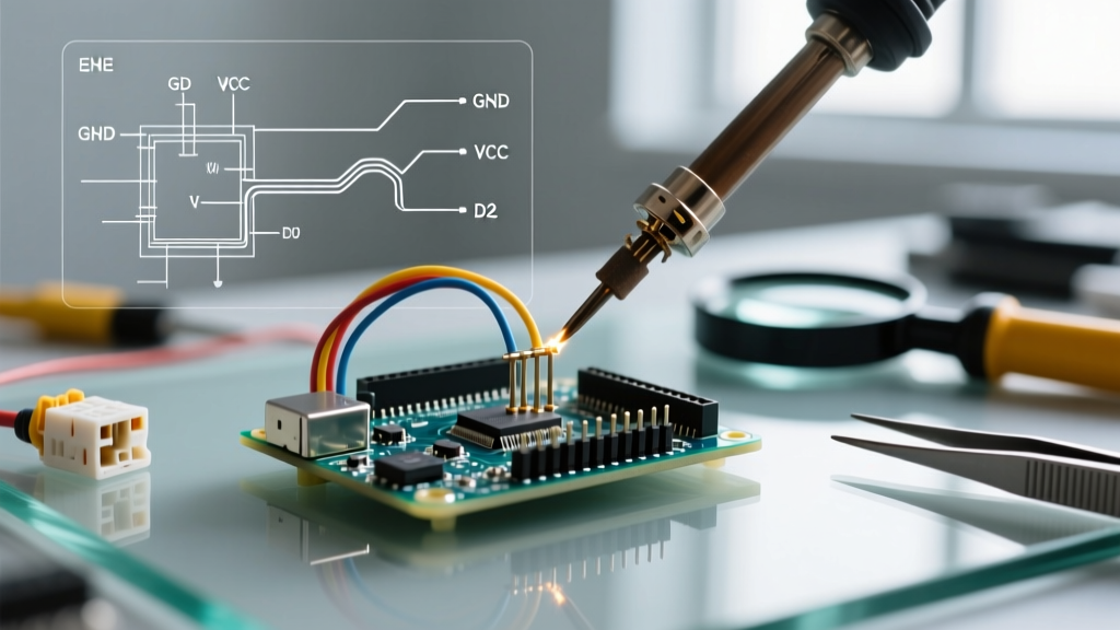
| Random Watchdog Resets during motor starts | EMI coupling into the reset pin or severe VCC brownout. | Shield the microcontroller enclosure. Add a 100nF ceramic capacitor directly across the VCC and GND pins of the MCU. |
| Analog sensor readings fluctuate wildly (±15%) | Ground loops or VFD high-frequency noise on the signal wire. | Use shielded twisted-pair (STP) cable for analog signals. Ground the shield at the PLC end ONLY. Implement a software moving-average filter. |
| Digital Inputs trigger falsely when nearby AC contactors engage | Capacitive coupling of AC noise into high-impedance digital input lines. | Add a 10kΩ pull-down resistor to ground on the input line, or place a 10nF ceramic capacitor in parallel with the input to filter high-frequency transients. |
| PLC freezes indefinitely without rebooting | Software deadlock or I2C bus lockup due to noise. | Enable the hardware Watchdog Timer (WDT). If using I2C sensors, implement an I2C bus recovery routine that toggles the SCL line to release stuck slave devices. |
Final Thoughts on Workflow Optimization
Using an Arduino as a PLC is no longer a 'hack'—it is a legitimate, cost-effective automation strategy when executed with industrial discipline. By selecting properly isolated hardware like the Arduino Opta or Industrial Shields ESP32, adopting IEC 61131-3 programming standards via OpenPLC, and rigorously hardening your electrical panels against EMI and inductive spikes, you can achieve enterprise-level reliability at a fraction of the traditional cost. The key to success lies not in the microcontroller itself, but in the engineering workflows you build around it.